Orthodontic self-locking bracket

A technology of self-locking brackets and brackets, applied in brackets, arch wires, etc., can solve the problems of large thickness of self-locking brackets, short and blunt bracket wings, and inability to open the sliding cover, and achieves good self-locking effect. , to avoid discomfort, cover firmly

Active Publication Date: 2015-01-28
SHANDONG UNIV
View PDF6 Cites 2 Cited by
  • Summary
  • Abstract
  • Description
  • Claims
  • Application Information

AI Technical Summary

Problems solved by technology

Because the structure of the sliding cover bracket is relatively complicated, the pins or blocks are tiny protruding parts, and there will be problems that the sliding cover cannot be opened or closed in clinical use, and the price is expensive; moreover, self-locking The self-locking device of the bracket usually occupies a large space, which makes the thickness of the self-ligating bracket larger and may fall off when chewing. At the same time, because the bracket wings of the self-ligating bracket are short and blunt, it is inconvenient to retain when adding ligation accessories , easy to slip

Method used


Image

  • Orthodontic self-locking bracket
  • Orthodontic self-locking bracket
  • Orthodontic self-locking bracket

Examples


Embodiment 1

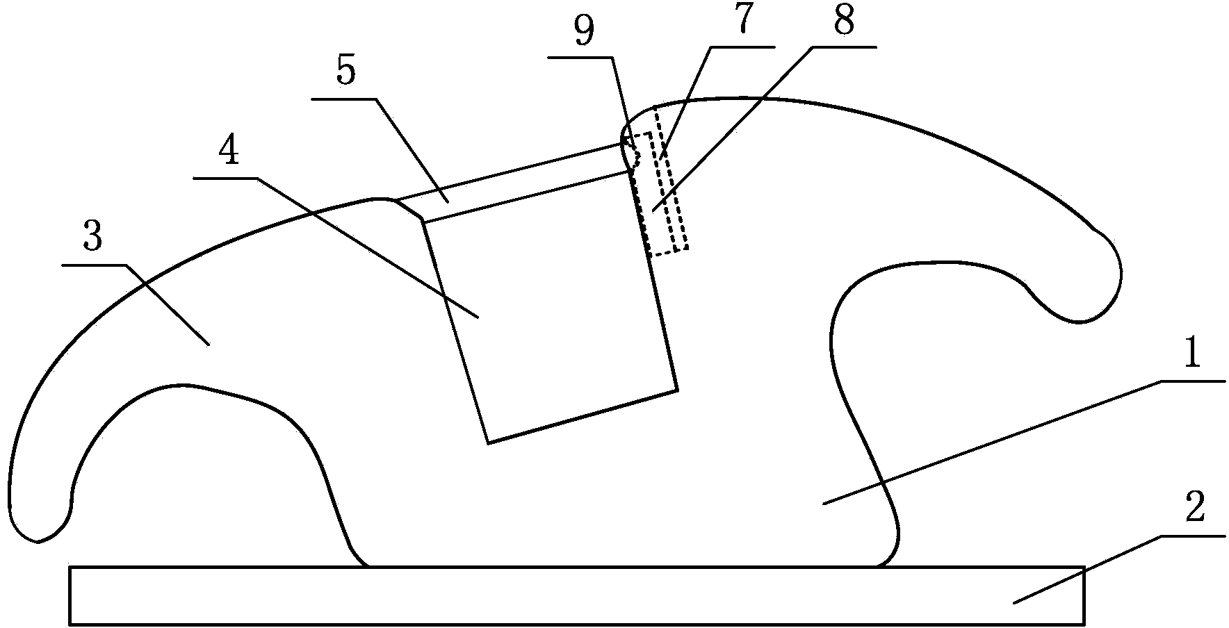
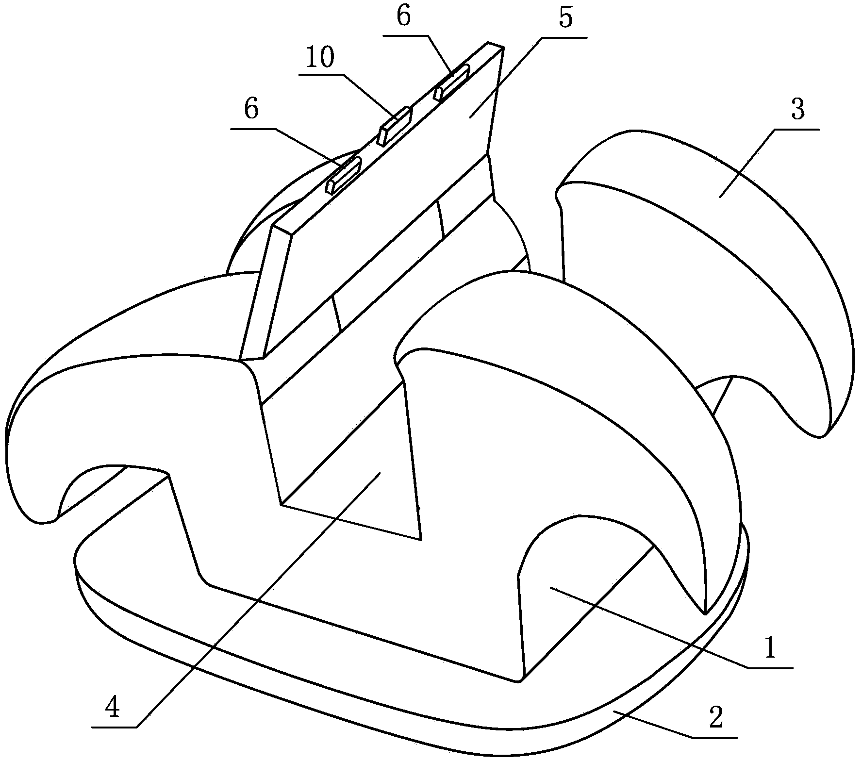
[0018] Such as Figure 1-2 As shown, an orthodontic self-ligating bracket includes a bracket base 1, a metal mesh bottom 2 is provided at the bottom of the bracket base 1, and a ligation wing 3 and an archwire groove 4 are provided on the bracket base 1. At the top of the archwire groove 4, there is a cover 5 arranged along the length direction of the archwire groove 4. One end of the cover 5 is movably connected with the top of the side wall of the archwire groove 4, and the other end of the cover 5 is A card protrusion 6 is respectively provided on both sides of the end face, a groove 7 is respectively provided on the two ligation wings 3 on the side opposite to the connecting end of the cover sheet 5, and an elastic plate 8 is respectively arranged in the two grooves 7, and an elastic plate 8 is arranged on the elastic plate 8. One side surface close to the archwire groove 4 is respectively provided with a locking groove 9 which matches with the corresponding locking protru...

Embodiment 2

[0025] Such as image 3 As shown, the difference between this embodiment and Embodiment 1 is that the elastic plate 8 is horizontally arranged in the groove 7, and one end of the elastic plate 8 is elastically connected to the inner wall of the groove 7 away from the archwire groove 4, and the elastic plate 8 A gap is provided between 8 and the bottom of the groove 7 . Others are the same as in Example 1.

[0026] When in use, first use a tool to withstand the protrusion 10 on the cover 5 and lift upwards, the two card protrusions 6 exert an upward force on the top of the card slot 9, the elastic plate 8 is deformed under pressure, bends to the top of the elastic plate 8, and the card is locked. The protrusion 6 slides out from the slot 9 of the elastic plate 8. After the protrusion 6 slides out of the slot 9, the elastic plate 8 returns to its original shape, the cover 5 is opened, and the archwire is put into the groove 4 of the arch wire. Similarly, when the cover sheet 5...


PUM


Abstract

The invention relates to an orthodontic self-locking bracket. The orthodontic self-locking bracket comprises a bracket matrix, wherein a metal net bottom is arranged at the bottom of the bracket matrix, the bracket matrix is provided with ligation wings and an arch wire ditch, the top of the arch wire ditch is provided with a cover slip which is arranged along the length direction of the arch wire ditch, one end of the cover slip is movably connected with the top part of the side wall of one side of the arch wire ditch, locking bulges are respectively arranged at the two sides of the end surface of the other end of the cover slip, and two grooves are respectively formed in the two ligation wings which are arranged at one side opposite to the connecting end of the cover slip and are internally provided with an elastic plate respectively. With the adoption of the orthodontic self-locking bracket, as the cover slip adopts a lifting type, force and reaction force during uncovering both disperse on the bracket, thus avoiding discomfort of teeth caused by abnormal force applied to the teeth, effectively avoiding the problem that the cover slip can not be opened or closed, greatly shortening clinic operation time of an orthodontic doctor, shortening treatment cycle of a patient and improving the rectification effect, so that when the aesthetic property and comfort of the orthodontic self-locking bracket are ensured, the orthodontic self-locking bracket also has the characteristics of stable structure, firm covering and good self-locking effect.

Description

Technical field: [0001] The invention relates to an orthodontic self-locking bracket. Background technique: [0002] Common self-locking brackets include sliding cover brackets and locking brackets. The sliding cover brackets are provided with sliding covers on both sides of the groove. , The stopper fixes the position of the sliding cover, so that the sliding cover and the groove together form a closed channel in which the arch wire can move flexibly, so the sliding cover bracket is also called passive self-locking bracket. Because the structure of the sliding cover bracket is relatively complicated, the pins or blocks are tiny protruding parts, and there will be problems that the sliding cover cannot be opened or closed in clinical use, and the price is expensive; moreover, self-locking The self-locking device of the bracket usually occupies a large space, which makes the thickness of the self-ligating bracket larger and may fall off when chewing. At the same time, becaus...

Claims


Application Information

Patent Timeline
Patent Type & Authority Applications(China)
IPC IPC(8): A61C7/34
Inventor 吕涛
Owner SHANDONG UNIV
Why Eureka
Try Eureka