
A flip-type pouring mold

A flip-type, mold technology, applied in the direction of manufacturing tools, casting mold handling equipment, casting molding equipment, etc., can solve the problems of inconvenient, compact and narrow operating space, and the design of the distance between the movable mold opening and the like. , to achieve the effect of smooth process and easy coating

Active Publication Date: 2016-06-01
SUZHOU MINGZHI TECH
View PDF9 Cites 0 Cited by
  • Summary
  • Abstract
  • Description
  • Claims
  • Application Information

AI Technical Summary

Problems solved by technology

[0002] Existing casting molds generally include a fixed mold part and a movable mold part. The mold cavity is formed after the movable mold part and the fixed mold part are closed. The aluminum alloy melt is injected into the formed cavity through a container, and then the mold is opened. The mechanism ejects the prepared products, thus realizing the purpose of mass production of products. When pouring complex products, in order to facilitate mold opening, it is often necessary to set up multiple sets of movable molds. In order to save space and reduce the overall volume of the pouring mold, the dynamic The mold opening distance will not be designed very large, so the operating space reserved for the movable mold and the fixed mold is generally relatively compact and narrow. It is not very convenient during the cleaning process

Method used


Image

  • A flip-type pouring mold
  • A flip-type pouring mold
  • A flip-type pouring mold

Examples


Embodiment 1

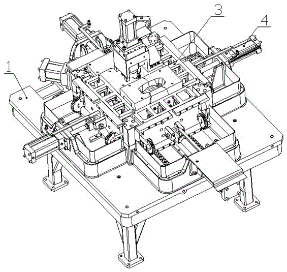
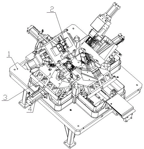
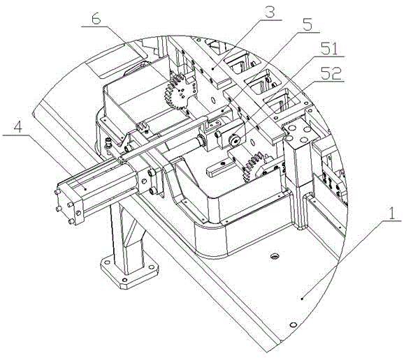
[0025] see Figure 1-Figure 6 , as shown in the legend therein, a flip-type pouring mold includes a workbench 1, a fixed mold and four movable mold devices, the fixed mold is a bottom mold 2 arranged on the workbench, and the movable mold device It includes a side mold 3 arranged on one side of the bottom mold 2 and a hydraulic cylinder 4 arranged on the workbench 1 and on the driving side of the side mold 3. The side mold 3 has a horizontal mold opening and closing direction, and the driving direction of the hydraulic cylinder The same as the above mold opening and closing direction,

[0026] A connecting plate 5 is arranged on the driving side of the side mold 3, and the connecting plate 5 is rotatably connected with the driving end of the hydraulic cylinder 4 and forms a rotation axis extending in the horizontal direction;

[0027] Side mold 3 also comprises turning mechanism, and this turning mechanism comprises the gear 6 that is arranged on the drive side of side mold 3...


PUM


Abstract

The invention discloses a flip-casting mold comprising a workbench, a fixed mold and at least two movable mold devices. The fixed mold is a bottom mold arranged on the workbench; the movable mold device comprises a side mold arranged on one side of the bottom mold and a drive component disposed on a drive side of the workbench; a connecting plate disposed on a drive side of the side mold is rotatablely connected with a drive end of the drive component and forms a rotation axis; a flip mechanism comprising a gear and a rack is disposed on the drive side of the side mold; a central axis and a rotation axis of the gear are coaxially disposed; the rack extends along the direction of opening and closing mold of the side mold; a bottom meshing position of the gear is positioned on an extension line of a meshing line of the rack; the direction between the rack and the side mold and along the direction of the opening and closing mold is greater than the the maximum size from the rotation axis to the edge of the side mold. With the casting mold, an original driving device is capable of realizing opening mold and flipping at the same time, and staff are capable of painting, cleaning, maintaining and inspecting a cavity of the movable mold easily.

Description

technical field [0001] The invention relates to a casting mold, in particular to an overturning casting mold. Background technique [0002] Existing casting molds generally include a fixed mold part and a movable mold part. The mold cavity is formed after the movable mold part and the fixed mold part are closed. The aluminum alloy melt is injected into the formed cavity through a container, and then the mold is opened. The mechanism ejects the prepared products, thus realizing the purpose of mass production of products. When pouring complex products, in order to facilitate mold opening, it is often necessary to set up multiple sets of movable molds. In order to save space and reduce the overall volume of the pouring mold, the dynamic The mold opening distance will not be designed very large, so the operating space reserved for the movable mold and the fixed mold is generally relatively compact and narrow. It is not very convenient during the cleaning process. Contents of ...

Claims


Application Information

Patent Timeline
Patent Type & Authority Patents(China)
IPC IPC(8): B22D33/04
CPCB22C9/00B22C17/08
Inventor 顾健
Owner SUZHOU MINGZHI TECH
Learn More