Grinding machine tail seat structure

A technology of bed tailstock and shell, applied in the direction of grinding workpiece support, etc., can solve problems such as excessive wear of the tip, bending deformation of the workpiece, etc., and achieve the effect of avoiding bending deformation and excessive wear of the tip

Inactive Publication Date: 2015-01-28
CHONGQING JINLUN IND
View PDF0 Cites 2 Cited by
  • Summary
  • Abstract
  • Description
  • Claims
  • Application Information

AI Technical Summary

Problems solved by technology

Since the workpiece will elongate due to thermal expansion during the grinding process, and the preload of the t

Method used


Image

  • Grinding machine tail seat structure

Examples


Embodiment Construction

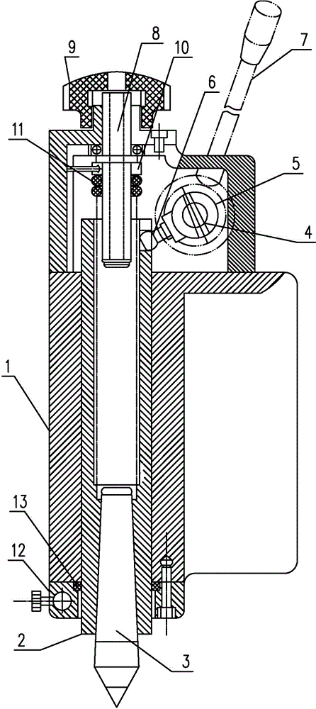
[0012] Below in conjunction with accompanying drawing and specific embodiment the present invention will be described in further detail:

[0013] Such as figure 1 As shown, a grinder tailstock structure includes a housing 1, the housing 1, a sleeve 2 and a top 3; The barrel 2 is fixed, and part of the top 3 and the sleeve 2 protrude from the casing 1; the tail of the casing 1 is provided with a rotating shaft 4, and a shaft sleeve 5 which is connected with the rotating shaft 4 is sleeved on the rotating shaft 4; a driving lever 6 is also included , one end of the lever 6 is fixed to the shaft sleeve 5, and the other end is fixed to the sleeve 2; a handle 7 is also provided on the rotating shaft 4; a screw 8 is provided at the tail of the housing 1, and one end of the screw 8 is embedded in the housing And connected with the other end of the sleeve 2, the other end of the lead screw 8 is left outside the housing 1 and connected with a handle 9, a nut 10 and a spring 11 are sle...


PUM


Abstract

The invention relates to the field of machining equipment, in particular to a grinding machine tail seat structure. The grinding machine tail seat structure comprises a casing, a sleeve and a center, wherein the sleeve is arranged in the casing, the center is arranged at one end of the sleeve, the tail part of the casing is provided with a rotating shaft, a shaft sleeve linked with the rotating shaft is connected onto the rotating shaft in a sleeving way, the grinding machine tail seat structure also comprises a shifting rod, one end of the shifting rod is fixedly arranged at the shaft sleeve, the other end of the shifting rod is fixedly arranged at the sleeve, a handle is also arranged on the rotating shaft, the tail part of the casing is provided with a lead screw, one end of the lead screw is embedded into the casing and is connected with the other end of the sleeve, the other end of the lead screw is arranged at the outside of the casing and is connected with the handle, a screw nut and a spring are connected onto the lead screw in a sleeving way, the screw nut is fixedly arranged on the casing through a pin element, one end of the spring is fixedly arranged at the screw nut, and the other end of the spring is fixedly arranged at the lead screw. The grinding machine tail seat structure adopting the technical scheme has the advantage that the pre-tightening force can be automatically adjusted.

Description

technical field [0001] The invention relates to the field of machining equipment, in particular to a grinder tailstock structure. Background technique [0002] The tailstock of the grinding machine mainly uses the tip installed on the tailstock and the tip of the grinding machine headstock to support the workpiece together, so as to realize the accurate positioning of the workpiece. When grinding, the tailstock is fastened on the inclined surface of the workbench with L-shaped screws. [0003] One of the biggest problems in the existing tailstock is that the pretightening force of the tailstock tip to the workpiece cannot be automatically adjusted. Since the workpiece will elongate due to thermal expansion during the grinding process, and the preload of the tip is fixed at this time, it is easy to cause bending deformation of the workpiece and excessive wear of the tip. Contents of the invention [0004] The invention aims to provide a grinder tail stock structure which ...

Claims


Application Information

Patent Timeline
IPC IPC(8): B24B41/06
CPCB24B41/06
Inventor 吴明喜
Owner CHONGQING JINLUN IND
Why Eureka
Try Eureka