Thrust plate reliability test device

A test device and reliability technology, applied in the field of thrust plate reliability test device, can solve the problems of no oil or dry friction on the thrust surface of the crankshaft, quality control consistency error, accelerated wear of the thrust plate, etc. The effect of adjustable size, simple installation and compact structure

Pending Publication Date: 2021-08-10
GUANGXI YUCHAI MASCH CO LTD
View PDF0 Cites 0 Cited by
  • Summary
  • Abstract
  • Description
  • Claims
  • Application Information

AI Technical Summary

Problems solved by technology

[0002] Existing commercial vehicles basically use engines with clutches, and there are quality control consistency errors in the manufacturing process. At the same time, in the process of use, every time the clutch is stepped on, the flywheel and crankshaft of the engine will be sent to the flywheel and crankshaft of the engine through the clutch. An axial force is generated. If the force is too large, the thrust surface of the crankshaft generates a large thrust, and the thrust surface of the crankshaft is prone to oil-free or dry friction, which will cause the wear of the thrust plate to accelerate
[0003] At present, there is no device for simulating the force generated by stepping on the clutch in the reliability test of the bench, and the influence test of the force generated by the clutch on the wear of the thrust plate cannot be done on the engine reliability bench. It is urgent to design a set of reliable thrust plates. The permanent test device is used to test the influence of the force generated by the clutch on the wear of the thrust plate

Method used


Image

  • Thrust plate reliability test device
  • Thrust plate reliability test device
  • Thrust plate reliability test device

Examples


Embodiment Construction

[0027] The present invention will be further described in detail below in combination with specific embodiments. It should be emphasized that the following description is only exemplary and not intended to limit the scope of the invention and its application.

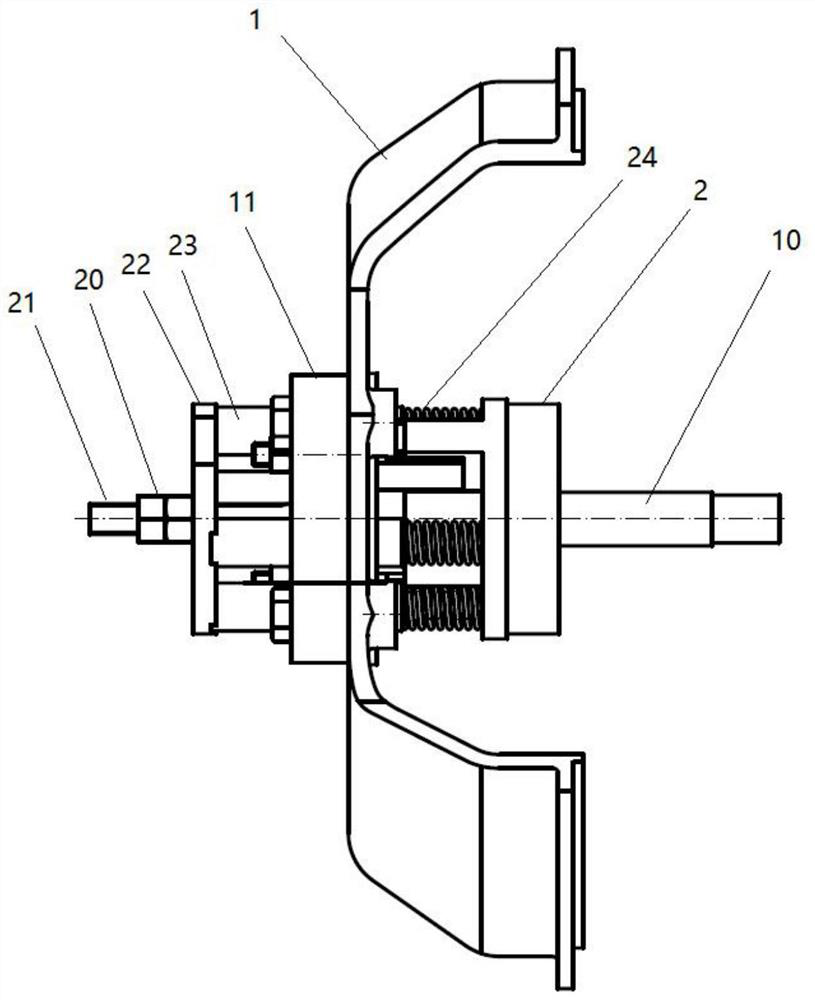
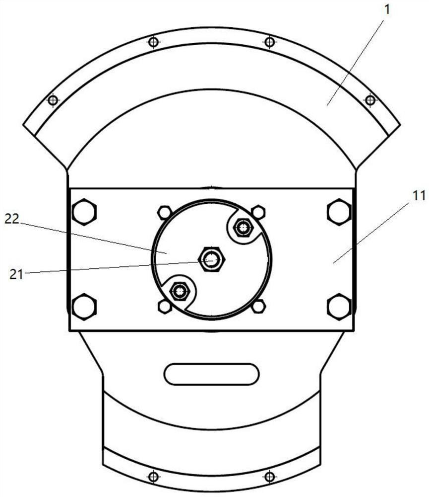
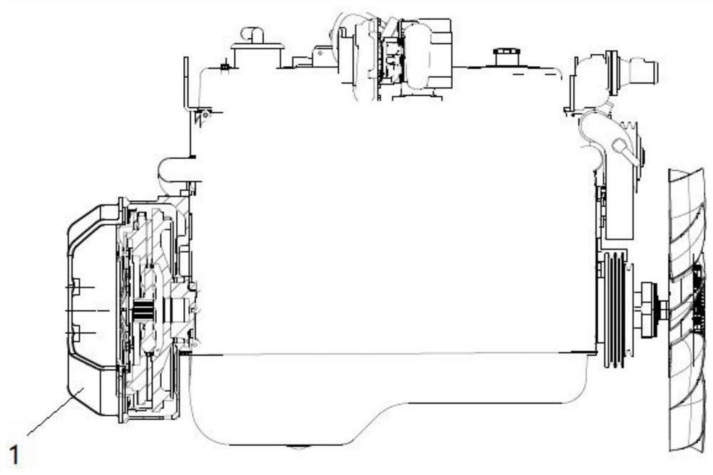
[0028] Such as Figure 1-12 As shown, the thrust plate reliability test device is characterized in that it includes a tooling clutch cover 1, a release bearing assembly 2, a positioning component 3, and a thrust adjustment component 4, and the middle part of the tooling clutch cover 1 is provided with a The positioning hole 5 is used for positioning the positioning assembly 3, and there are notches 6 on both sides of the tooling clutch cover 1, which is convenient for installation and observation of the device; the center of the release bearing assembly 2 is provided with a round hole 7, and the release bearing One end of the assembly 2 is provided with two symmetrical limit ends 8 and four symmetrical spring circular ...


PUM


Abstract

The invention discloses a thrust plate reliability test device, which is characterized in that the thrust plate reliability test device comprises a tool clutch cover, a release bearing assembly, a positioning assembly and a thrust adjusting assembly, a positioning hole is formed in the middle of the tool clutch cover, a round hole is formed in the center of the release bearing assembly, one end of the release bearing assembly is provided with two symmetrical limiting ends and four symmetrical spring circular grooves, the positioning assembly is installed in the middle of the tool clutch cover, the thrust adjusting assembly is distributed on the left portion of the positioning assembly, the release bearing assembly is installed on the right portion of the positioning assembly, and the thrust adjusting assembly is matched with the release bearing assembly. The thrust plate reliability test device has the advantages of being compact in structure, easy to install, adjustable in stress, capable of being connected with an engine for real operation test and accurate in test result.

Description

technical field [0001] The invention relates to the field of engine assembly tests, in particular to a thrust plate reliability test device. Background technique [0002] Existing commercial vehicles basically use engines with clutches, and there are quality control consistency errors in the manufacturing process. At the same time, in the process of use, every time the clutch is stepped on, the flywheel and crankshaft of the engine will be sent to the flywheel and crankshaft of the engine through the clutch. An axial force is generated. If the force is too large, the thrust surface of the crankshaft generates a large thrust, and the thrust surface of the crankshaft is prone to oil-free or dry friction, which will cause the wear of the thrust plate to accelerate . [0003] At present, there is no device for simulating the force generated by stepping on the clutch in the reliability test of the bench, and the influence test of the force generated by the clutch on the wear of ...

Claims


Application Information

Patent Timeline
Patent Type & Authority Applications(China)
IPC IPC(8): G01N3/56G01N3/02G01N3/04F16D23/14
CPCF16D23/142G01N3/02G01N3/04G01N3/56G01N2203/0005G01N2203/0035G01N2203/0282
Inventor 廖跃辉杨剑峰刘伟森杨海
Owner GUANGXI YUCHAI MASCH CO LTD
Why Eureka
Try Eureka