Crankshaft balance weight fan blade chamfering mechanism

A technology of chamfering mechanism and counterweight, which is applied in the field of chamfering mechanism and crankshaft counterweight fan blade chamfering, which can solve the problem of dimensional accuracy and surface roughness of crankshaft workpieces that are difficult to meet requirements, increase production costs, and large tool loss, etc. Problems, to achieve significant economic benefits, simple installation, high processing accuracy

Inactive Publication Date: 2015-06-17
荆州环球汽车零部件制造有限公司
View PDF3 Cites 1 Cited by
  • Summary
  • Abstract
  • Description
  • Claims
  • Application Information

AI Technical Summary

Problems solved by technology

[0002] In the process of producing the crankshaft, it is often required to chamfer or round the circumference of the counterweight fan blade in sections, so as to avoid the burr on the circumference of the counterweight fan blade and play an aesthetic role at the same time. For the crankshaft workpiece with segmental chamfering (round), the counterweight fan blade segmental chamfering (circle) processing is performed with a general-purpose tool. The dimensional accuracy and surface roughness of the crankshaft workpiece are often difficult to meet the requirements, and the loss of the tool is too large, and the investment cost It is too high, and because of the various waste products produced in this process, the production cost is greatly increased. Therefore, a low-cost, high-efficiency, segmented chamfering (circle) mechanism for crankshaft counterweight fan blades suitable for ordinary machine tools has been developed. Has great application value

Method used


Image

  • Crankshaft balance weight fan blade chamfering mechanism
  • Crankshaft balance weight fan blade chamfering mechanism
  • Crankshaft balance weight fan blade chamfering mechanism

Examples


Embodiment Construction

[0017] The present invention will be described in detail below in conjunction with the accompanying drawings and embodiments.

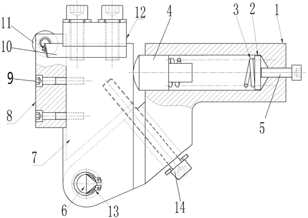
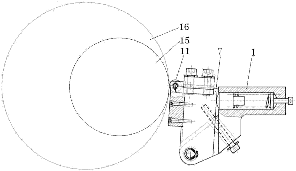
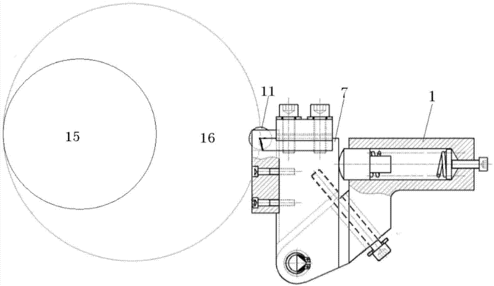
[0018] The crankshaft counterweight fan blade chamfering mechanism provided by the invention has a structure such as figure 1 As shown, it includes a cutting unit and a flexible tool letting unit located behind the cutting unit. The cutting unit includes a tool body 7, a positioning block 8, two knives 10, a pressing block 12 and a rolling member 11 installed in the positioning block. The parts are rollers or rolling bearings. The cutter body is in the shape of a square column. The pressure block 12 is fixed on the top of the cutter body by screws 9. The two cutters are symmetrically fixed on the bottom surface of the pressure block along the horizontal direction and are located on the upper part of the left and right sides of the cutter body. , the positioning block is a square column type, the positioning block 8 is fixed on the front side of the cu...


PUM


Abstract

The invention provides a crankshaft balance weight fan blade chamfering mechanism. The crankshaft balance weight fan blade chamfering mechanism comprises a cutting unit and a flexible cutter receding unit located behind the cutting unit. The cutting unit comprises a square-column-shaped cutter body, a positioning block fixed to the front side face of the cutter body, two cutters and a rolling piece, wherein the two cutters are symmetrically fixed to the upper portion of the left side face and the upper portion of the right side face of the cutter body in the horizontal direction, the rolling piece is installed at the front end of the top end of the positioning block through a pin shaft, and the rolling face of the rolling piece protrudes out of the front side face of the positioning block and is located in front of cutter blades. The flexible cutter receding unit comprises a cutter holder, an ejector block installed in the cutter holder, a compressed spring, a baffle and an adjusting threaded rod fixedly connected with the baffle, wherein the bottom end of the cutter holder is hinged to the bottom end of the cutter body. The chamfering mechanism has the advantages of being easy to install, convenient to use, high in machining precision and capable of reducing the loss of the cutters and waste products; the chamfering mechanism is used for conducting chamfering on a crankshaft balance weight fan blade, the machining cost can be greatly reduced, the product quality can be fully guaranteed, and the obvious economic benefits are achieved.

Description

technical field [0001] The invention relates to a chamfering mechanism, in particular to a mechanism for chamfering crankshaft counterweight fan blades, and belongs to the technical field of crankshaft processing equipment. Background technique [0002] In the process of producing the crankshaft, it is often required to chamfer or round the circumference of the counterweight fan blade in sections, so as to avoid the burr on the circumference of the counterweight fan blade and play an aesthetic role at the same time. For the crankshaft workpiece with segmental chamfering (round), the counterweight fan blade segmental chamfering (circle) processing is performed with a general-purpose tool. The dimensional accuracy and surface roughness of the crankshaft workpiece are often difficult to meet the requirements, and the loss of the tool is too large, and the investment cost It is too high, and because of the various waste products produced in this process, the production cost is g...

Claims


Application Information

Patent Timeline
Patent Type & Authority Applications(China)
IPC IPC(8): B23D79/00
Inventor 范朝阳吴飞
Owner 荆州环球汽车零部件制造有限公司
Why Eureka
Try Eureka