Fixed shaft compass

A compass and fixed-axis technology, applied in the field of fixed-axis compasses, can solve the problems of enlarged holes, unclear circles, damage, etc., and achieve the effect of uniform and clear lines

Inactive Publication Date: 2015-01-28
黄赞谟
View PDF6 Cites 10 Cited by
  • Summary
  • Abstract
  • Description
  • Claims
  • Application Information

AI Technical Summary

Problems solved by technology

However, after drawing multiple circles or arcs at the center of a circle, and after piercing a point with a needle point and rotating it several times, the paper where the point is located during the rotation process will produce an obvious hole, and the hole will become larger. It is not accurate, the paper is also damaged, and the subsequent use process is also prone to damage
[0003] Since the current compasses maintain the rigidity at both ends of the radius, the foot of the compass at the end of the circle is fixedly connected to the compasses without cushioning. The brush needs to be pressed down to make it stick to the paper. Excessive force on the end of the brush may easily cause the tip of the pen to break or scratch the paper. On the other hand, if the pen tip encounters an obstacle on the uneven paper surface, the needle tip at the center of the circle will jump away from the center of the circle, causing the compasses to not be smooth in the circle drawing process.
If the force of the two compasses is unbalanced and the force is too large at the center of the circle, the force of the brush tip is too small, which will cause the circle to be unclear
In the actual circle drawing process, it is difficult to maintain uniform force at the tip of the pen, resulting in uneven and unclear lines

Method used


Image

  • Fixed shaft compass
  • Fixed shaft compass

Examples


Embodiment Construction

[0018] Embodiments of the present invention are described in detail below.

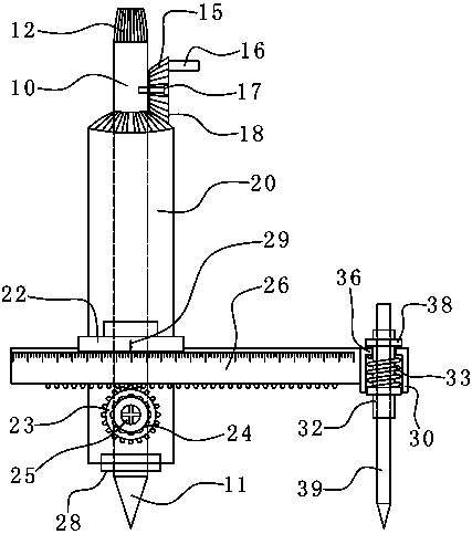
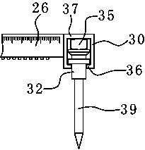
[0019] refer to figure 1 , figure 2 As shown, the present invention is a fixed axis compass, which includes a fixed vertical shaft 10, a rotating sleeve 20 rotatably sleeved on the fixed vertical shaft 10, a sleeve rail 22 fixedly connected to the side of the rotating sleeve 20, and sleeved on the The sleeve rail 22 is a cross bar that can slide laterally, and a pen holder 32 that can be elastically connected to the end of the cross bar longitudinally. Set the fixed vertical shaft 10 to prevent the needle point at the lower end of the vertical shaft from stabbing the paper surface during rotation, and protect the paper surface. The rotating sleeve 20 connects the sleeve rail 22 and the cross bar so that the cross bar can move laterally and choose a circle or an arc. radius, rotate the rotating sleeve 20 to draw circles or arcs on the paper, and the pen for drawing circles or arcs is connected to th...


PUM


Abstract

The invention discloses a fixed shaft compass. The fixed shaft compass comprises a fixed vertical shaft, a rotary sleeve which can sleeve the fixed vertical shaft in a rotatable mode, a sleeve rail which is fixedly connected to the lateral portion of the rotary sleeve, a cross rod which sleeves the sleeve rail and can horizontally slide and a pen clamping sleeve which can be longitudinally connected to the tail end of the cross rod in an elastic mode. According to the fixed shaft compass, the fixed vertical shaft is arranged to avoid a needle point at the lower end of the vertical shaft from puncturing paper during a rotation process and the fixed vertical shaft plays a role in protecting the paper; the rotary sleeve is connected with the sleeve rail and the cross rod, the cross rod can horizontally move to select the drawing radius of a circle or an arc shape, the circle or a camber line can be drew on the paper by rotating the rotary sleeve, a pen for drawing the circle or the camber line is connected to the tail end of the cross rod through the pen clamping sleeve and has elasticity in the longitudinal direction, namely the pen can slightly move in the longitudinal direction, the compass has an elastic downward pressing force to the pen during the process of drawing the circle or the arc, the pen has tiny extension, a pen tip is tightly adhered to the paper, and accordingly a uniform and clear line can be drew and the paper is not punctured and scraped.

Description

technical field [0001] The invention relates to a stationery, in particular to a fixed axis compasses. Background technique [0002] The most conventional compasses have two legs spread apart, one leg has a needle point as the center of rotation, that is, the center of a circle or arc, and the other leg holds the pencil lead, and the compass is rotated so that it holds the pencil lead. Turn the foot around the foot where the needle point is to draw an arc or circle. However, after drawing multiple circles or arcs at the center of a circle, and after piercing a point with a needle tip and rotating it several times, the paper where the point is located during the rotation process will produce an obvious hole, and the hole will become larger. It is not accurate, the paper is also damaged, and it is easy to cause damage during subsequent use. [0003] Since the current compasses maintain the rigidity at both ends of the radius, the foot of the compass at the end of the circle ...

Claims


Application Information

Patent Timeline
Patent Type & Authority Applications(China)
IPC IPC(8): B43L9/02
CPCB43L9/02
Inventor 黄赞谟
Owner 黄赞谟
Why Eureka
Try Eureka