Controllable release system

A conveying system and equipment technology, applied in the field of controllable release systems, can solve the problems of inability to respond in a timely manner to the transmission of thrust, uneven transmission of force, and easy occurrence of off-axis, so as to avoid knotting or intertwining, Avoid knots or tangles and achieve controllable effects

Pending Publication Date: 2020-03-31
NINGBO DIOCHANGE MEDICAL TECH CO LTD
View PDF0 Cites 7 Cited by
  • Summary
  • Abstract
  • Description
  • Claims
  • Application Information

AI Technical Summary

Problems solved by technology

[0008] Second, the collection device is not directly connected to the bracket, but is connected through a collar connected to the distal restraint. This method is likely to cause uneven force transmission, and the device is prone to off-axis when retracting the sheath. In the process of being pushed into the sheath and being pushed to the target position, the transmission of the thrust cannot be responded in time, and it may even cause the operator to continue to push the sheath handle outside the body, but the stent has not been pushed out from the distal end of the sheath for a long time.

Method used


Image

  • Controllable release system
  • Controllable release system
  • Controllable release system

Examples


Embodiment 1

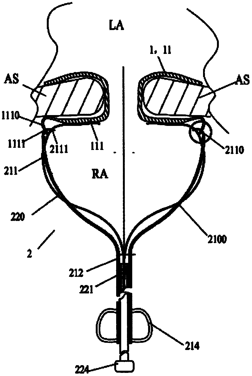
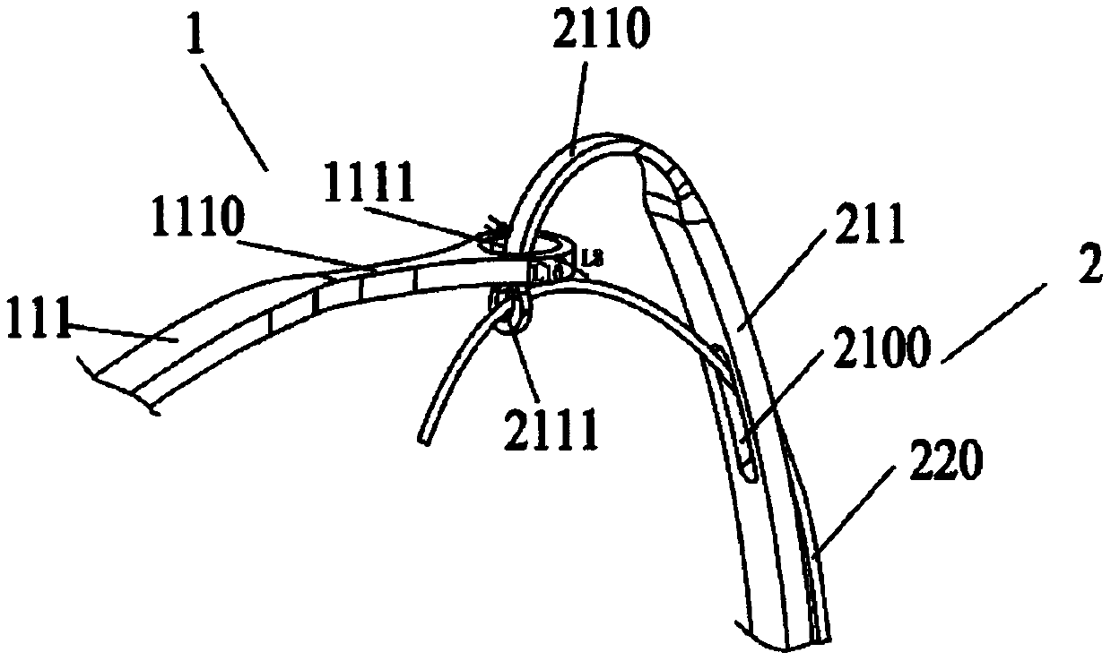
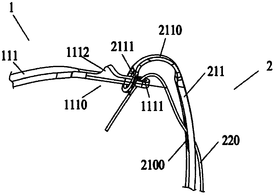
[0071] Such as figure 1 As shown, the controlled release system provided by the present invention includes an implant device 1 and a delivery system 2 . The proximal region of the implant instrument 1 is provided with a plurality of first holes 1111, and the delivery system 2 includes a plurality of traction rods 211 and a plurality of release wires 220, a plurality of release wires 220, a plurality of traction rods 211 and a plurality of first holes 1111 correspond to each other in quantity and position, and each traction rod 211 is provided with a second hole 2111 and a binding member 210, the second hole 2111 is located at the far end of the traction rod 211, and the binding member 210 is located in the second hole 2111 The proximal end side of the device, the first hole 1111 provided on the implant instrument 1 and the second hole 2111 provided on the traction rod 211 can interpenetrate with each other, and the release wire 220 passes through the binding member 210, the fi...

Embodiment 2

[0095] On the basis of Embodiment 1, as a special implementation example, the implant device 1 is an elastic ostomy stent 11 that can be placed at the interatrial septum, and the delivery system 2 is used to transfer the elastic ostomy stent 11 from Delivered in vitro with controlled release into the atrial septum. Specifically, the elastic pore-making scaffold 11 is a three-dimensional corrugated and / or net-like structure formed by interconnecting a plurality of support rods 111, and the three-dimensional corrugated and / or net-like structure includes a left disc that fits with the interatrial septal surface in the left atrium cavity. , the right disc that fits the interatrial septum in the right atrium cavity, and the waist that is arranged between the left disc and the right disc and is fixedly connected to the left disc and the right disc, and a through hole is arranged in the waist, and the through hole makes the left disc The atrium and the right atrium can be fluidly con...

Embodiment 3

[0110] Based on Embodiment 1, the difference between Embodiment 3 and Embodiment 1 is that the restraint member 210 is not a restraint hole 2100 provided on the drawbar 211 , but a restraint pipe 2101 or restraint ring 2102 is provided on the drawbar 211 .

[0111] In one embodiment, as Figures 4a-4c As shown, the binding member 210 is a binding tube 2101 with a hollow tubular structure, and the binding tube 2101 is sleeved outside the drawbar 211. The binding tube 2101 is preferably made of polymer tubes such as FEP, PTFE, PE, POE, PET, and silica gel. It can accommodate at least one traction rod 211 and one release wire 220 at the same time, which not only enhances the fit between the release wire 220 and the draw rod 211, but also enables the release wire 220 to pass through the lumen of the restraint tube 2101 smoothly and can be placed in the restraint tube 2101 At the same time, avoid opening holes on the traction rod 211, to a certain extent increase the anti-deformat...


PUM


Abstract

The application relates to a controllable release system comprising an implantation instrument and a conveying system. A plurality of first holes are formed in the near-end area of the implantation instrument. The conveying system includes a plurality of traction rods and a plurality of release wires; the plurality of release wires, the plurality of traction rods and the plurality of first holes are in one-to-one correspondence in number and position; each traction rod is provided with a second hole and a constraint part; the second holes are formed in the far ends of the traction rods; the release wires penetrate the constraint parts and the first holes or the second holes to realize connection between the implantation instrument and the conveying system. During the conveying process, theconstraint parts can limit movement of the release wires; and when the implantation instrument is released, the release wires can move relative to the traction rods. According to the system, the implantation instrument is convenient to repeatedly recover timely before dismounting of the implantation instrument; and during the releasing process, the implantation instrument can slowly stretch to anoptimal form from a sheath tube, detachable connection can be realized by withdrawing the release wires to realize the controllable release function. The system is simple in overall structure, convenient to operate, safe and reliable.

Description

technical field [0001] This application relates to the technical field of medical devices, in particular to a controllable release system. Background technique [0002] Minimally invasive transcatheter treatment of cardiovascular diseases has gradually become the main treatment method. Among them, such as coronary stents, heart valves, occluders, great vessel stents and other cardiovascular implanted devices, implanted devices need to be delivered to the The ideal position for human anticipation. The surgical operation process is generally to compress and deform the implanted device and load it into the delivery catheter, and use the structural design of the delivery catheter and / or the internal jacking tube to realize that the position of the implanted device in the delivery catheter remains relatively unchanged. With the aid of a guide wire or other imaging equipment, the implanted device is delivered to the target location through the delivery catheter, and then the impl...

Claims


Application Information

Patent Timeline
Patent Type & Authority Applications(China)
IPC IPC(8): A61B17/00A61F2/24A61F2/95
CPCA61B17/0057A61B2017/00252A61B2017/00526A61B2017/00575A61B2017/00592A61B2017/00606A61B2017/00623A61B2017/00867A61F2/2412A61F2/95A61F2002/9528
Inventor 董娟李彪胡晓明陈超李佳楠
Owner NINGBO DIOCHANGE MEDICAL TECH CO LTD
Why Eureka
Try Eureka