
Label automatic sticking device dedicated to blood collection tubes

A technology for blood collection tubes and labels, which is applied in the field of automatic label sticking devices, can solve the problems of complex device structure, low device efficiency, and low execution efficiency, and achieve the effects of simple device structure, convenient operation, and improved operating efficiency

Active Publication Date: 2017-02-22
SHANGHAI JINYU LUOBO ELECTRONICS TECH
View PDF3 Cites 0 Cited by
  • Summary
  • Abstract
  • Description
  • Claims
  • Application Information

AI Technical Summary

Problems solved by technology

The device structure is complex and the efficiency is low
[0003] Specifically, the existing blood collection tube label sticking technology needs to perform a variety of action steps as follows: obtain the test tube, clamp the test tube, roll the test tube, supply the label, compress the label, complete the pasting and release the test tube; the various steps bring the following Problem: The structure of the device is complex, because all single-step actions require power devices and transmission mechanisms, so the device structure is more complicated; the execution efficiency is low, because all single-step actions need to be executed in sequence, so the device efficiency is low

Method used


Image

  • Label automatic sticking device dedicated to blood collection tubes
  • Label automatic sticking device dedicated to blood collection tubes
  • Label automatic sticking device dedicated to blood collection tubes

Examples


Embodiment 1

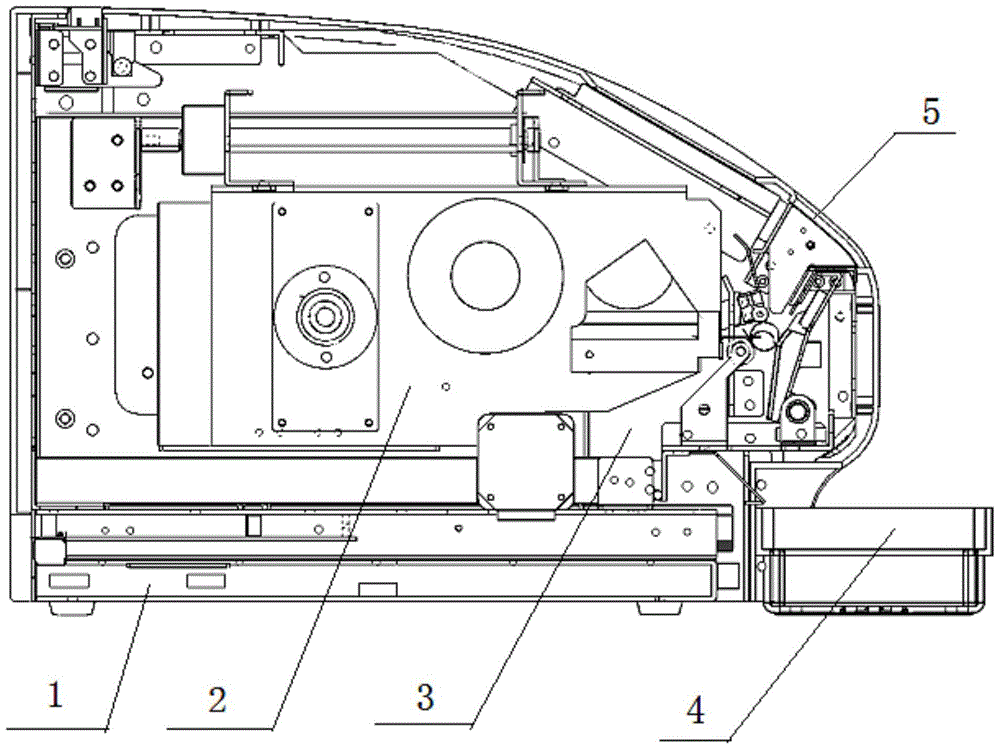
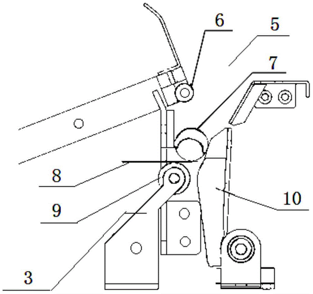
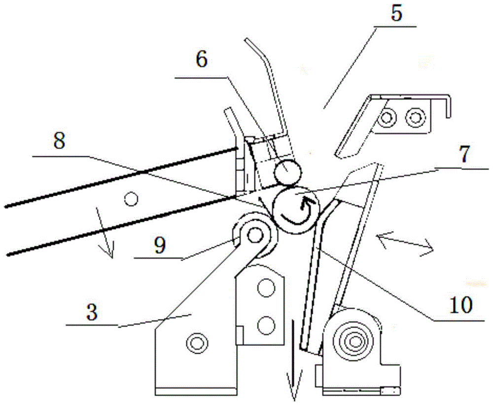
[0022] Embodiment 1: as attached figure 1 As shown, there is an input port 5 on the upper side of the front part of the body 1, a storage device 4 is installed under the front part of the body 1, a label printer 2 is installed in the middle of the body 1, and an extrusion labeling device 3 is installed below the input port 5 in the body 1 , at the same time, as attached figure 2 As shown, the extrusion labeling device 3 includes extrusion rollers 6 and driven wheels 9 correspondingly installed on the upper and lower positions, and elastic damping baffles 10 are installed on the outside of the extrusion rollers 6 and driven wheels 9, and the storage device 4 is in the The upper and lower sides between the rolling wheel pair formed by the extrusion roller 6 and the driven wheel 9 and the elastic damping baffle 10 are open and correspond to the input port 5 and the storage device 4 respectively.

[0023] In the foregoing, the squeeze roller 6 is above the driven wheel 9 .

[0...


PUM


Abstract

The invention relates to a special automatic label pasting device for a blood collection tube, wherein a throwing hole (5) is formed at the upper side of the front of a machine body (1); a storage device (4) is arranged below the front of the machine body (1); a label printer (2) is arranged in the middle of the interior of the machine body (1); an extrusion labeling device (3) is arranged under the throwing hole (5) in the machine body (1); the extrusion labeling device (3) internally comprises an extrusion rolling shaft (6) and a driven wheel (9) which are correspondingly arranged up and down; an elastic damping baffle (10) is arranged at the outer sides of the extrusion rolling shaft (6) and the driven wheel (9); rolling wheel pairs, formed on the extrusion rolling shaft (6) and the driven wheel (9), of the storage device (4) are respectively arranged above and under the elastic damping baffle (10) and respectively correspond to the throwing hole (5) and the storage device (4). After the automatic label pasting device is used, the labeling action is completed under the single extrusion action, so that the mechanical structure is greatly simplified, and the running efficiency is greatly improved; the device is suitable for pasting a label on other types of thin cylindrical objects such as a test tube.

Description

technical field [0001] The invention relates to a labeling equipment device for blood collection tubes in IPC International Patent Classification B65C labeling or labeling machinery, devices or methods, especially an automatic labeling device specially used for blood collection tubes. Background technique [0002] The label sticking technology in the known technology is to use the clamping device to support and clamp the target object from the inside or the outside, such as taking a blood collection test tube as an example, so that the test tube is rotated; then the label is supplied, and the driven roller is pressed to complete the label. Sticking action; finally the test tube needs to be released and a new test tube re-clamped. The device structure is complicated and the efficiency is low. [0003] Specifically, the existing blood collection tube label sticking technology needs to perform a variety of action steps as follows: obtain the test tube, clamp the test tube, rol...

Claims


Application Information

Patent Timeline
Patent Type & Authority Patents(China)
IPC IPC(8): B65C3/02B65C9/36
CPCB65C3/02B65C9/36
Inventor 金宇东陈鹏
Owner SHANGHAI JINYU LUOBO ELECTRONICS TECH
Learn More