
LED (light-emitting diode) lamp forming process

A molding process and LED lamp technology, applied in the field of LED lighting, can solve problems such as complex manufacturing process and environmental pollution, and achieve the effect of easy bending and forming, convenient bending, and improved appearance and display effect

Active Publication Date: 2015-01-28
SHANGHAI TOPLITE TECH
View PDF7 Cites 1 Cited by
  • Summary
  • Abstract
  • Description
  • Claims
  • Application Information

AI Technical Summary

Problems solved by technology

[0002] In the prior art, most of the LED bulbs only partially emit light, and the frosted lampshade is used. Most of the lamp body is occupied by the heat sink and the power supply device. In some occasions (such as crystal chandeliers and scene lights), the use of ordinary LED bulbs cannot replace traditional bulbs. To achieve full-angle lighting, the area of ​​​​the bulb must be increased, and the increase in the area of ​​the bulb corresponds to the radiator. It will be reduced. Quanzhouguang products on the market are all in the form of analog filaments, which conduct heat through gas or liquid. The use of this heat dissipation has certain limitations, and it will cause certain pollution to the environment. At the same time, the manufacturing process is relatively complicated.
At present, the sale of traditional incandescent lamps is banned. How to use LED bulbs to completely replace traditional incandescent lamps to achieve the same lighting effect as traditional bulbs has a certain technical blankness.

Method used


Image

  • LED (light-emitting diode) lamp forming process
  • LED (light-emitting diode) lamp forming process
  • LED (light-emitting diode) lamp forming process

Examples


Embodiment Construction

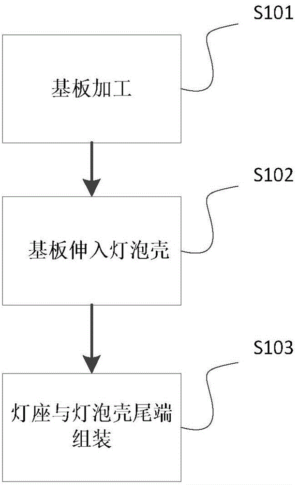
[0045] Combine figure 1 In the illustrated embodiment, those skilled in the art understand that the process flow for assembling the LED lamp provided by the present invention is preferably achieved through the following steps:

[0046] First, perform step i. Process the substrate 2 to adapt it to the shape of the bulb shell (1) of the LED lamp. Those skilled in the art understand that the LED lamp provided by the present invention includes a substrate 2 and an LED bulb shell 1. The substrate 2 is attached to the LED bulb shell 1, specifically as described in step ii below. Therefore, the substrate 2 needs to be processed so that its shape is compatible with the LED bulb shell 1. For example, preferably, the LED bulb shell 1 is in the shape of a gourd, that is, the middle part of the LED bulb shell 1 is thick, and the tail part and the front part are relatively smoothly transitioned and reduced. At this time, the substrate 2 is attached to the When inside the LED bulb shell 1, it...


PUM


Abstract

The invention provides an LED (light-emitting diode) lamp forming process. The LED lamp forming process is characterized by comprising the following steps of i, processing a substrate (2) to enable the substrate (2) to be matched with a bulb (1) of an LED lamp in shape, wherein an LED luminous chipset (3) is attached to the substrate (2); ii, allowing the substrate (2) to extend into the bulb (1) to enable the front end of the substrate(2) to extend along the inner wall of the bulb (1) and to be attached to the inner wall of the bulb (1); iii, assembling a lamp base (4) with the tail end of the bulb (1) to enable the bulb (1) and the lamp base (4) to form an enclosed space. By acting force between the substrate and the bulb of the LED lamp, the substrate is unfolded and is attached in the bulb of the LED lamp. Compared with the traditional LED lamp, the LED lamp has the advantages that the display effect of the LED lamp is improved, and the LED lamp has more advantages in market competition.

Description

Technical field [0001] The invention relates to the field of LED lighting, in particular to an LED lamp, and in particular to an LED lamp molding process. Background technique [0002] Most of the LED bulbs in the prior art only partially emit light. The frosted lampshade is used. Most of the lamp body is occupied by the heat sink and power supply device. The structure of the lamp body is too large. The area of ​​the traditional bulb bulb is about 90%. In some occasions (such as crystal chandeliers and scene lights), the use of ordinary LED bulbs cannot replace traditional bulbs. To achieve full-angle light emission, the area of ​​the bulb must be increased, and the area of ​​the bulb must increase corresponding to the heat sink It will reduce. All-peripheral light products on the market adopt the form of simulated filament, which conducts heat through gas or liquid. The use of this heat dissipation has certain limitations, which will cause certain pollution to the environment, a...

Claims


Application Information

Patent Timeline
Patent Type & Authority Applications(China)
IPC IPC(8): F21S2/00F21V19/00F21V17/00F21Y101/02
CPCF21K9/90
Inventor 李建胜
Owner SHANGHAI TOPLITE TECH
Learn More