AI technical title is built by PatSnap AI team. It summarizes the technical point description of the patent document.
A bender and bending technology, applied in the field of steel wire benders, can solve the problems of waste of steel wire, injury of construction personnel, poor bending quality, etc., and achieve the effects of convenient use, labor saving, labor intensity reduction, and production efficiency improvement.
Active Publication Date: 2017-08-04
STATE GRID CORP OF CHINA +1
View PDF13 Cites 0 Cited by
Summary
Abstract
Description
Claims
Application Information
AI Technical Summary
This helps you quickly interpret patents by identifying the three key elements:
Problems solved by technology
Method used
Benefits of technology
Problems solved by technology
[0002] When laying and erecting power cables, the electric power department often faces many difficulties in the daily cable production process due to the lack of effective tooling equipment
Among them, the bending of steel wires in UT clamps and wedge-shaped clamps has always been the most troublesome problem for construction workers. The production process basically relies on manpower. Manual bending is laborious, and strong bending can easily cause damage to the steel wires, resulting in waste of steel wires. , so that the steel wire cannot be perfectly wedged with the wire clip tongue; due to the use of manual bending, the cross-sectional area is large, and when the wire is very hard, manual bending is likely to cause injuries to the face, eyes, hands and other parts of the construction personnel
At the same time, due to the lack of effective tools and equipment for bending steel wires, the bending quality is poor, and sometimes even rework is required, and the operating efficiency is low, which greatly affects labor productivity and bending quality.
Method used
Image
Click on the blue label to locate the original text in one second.
Reading with bidirectional positioning of images and text.
Examples
Embodiment Construction
[0009] The technical solutions of the present invention will be further described below in conjunction with the accompanying drawings and embodiments.
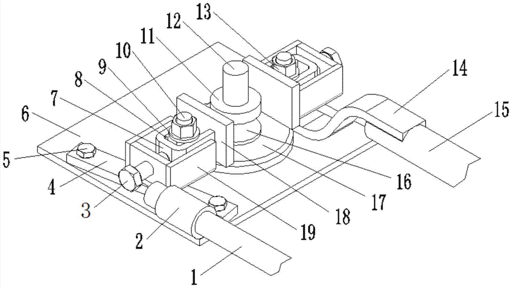
[0010] A steel wire bender, see attached figure 1 , including a fixed rod 1, a fixed rod seat 2, a fixed plate 4, a fixed bolt 5, a base 6, a bending seat, a bending head 11, a mandrel 12, a bending plate 14, a booster rod 15 and a turntable 17. There are two curved seats, including a fixed curved seat and a movable curved seat, which are symmetrically arranged relative to the mandrel 12. The curved seats include locking screws 3, U-shaped blocks 7, fixed gaskets 8, washers 9. Studs 10, nuts 13, connecting plates 18 and fixing seats 19. Wherein, the connecting plate 18 and the U-shaped block 7 are welded together to form a U-shaped seat, and the U-shaped seat passes through the stud 10 arranged on the fixed seat 19 and is packed into the fixed seat 19, and is connected with the nut 13 and the washer 9. The fixed seat 19 is f...
PUM
Abstract
The invention discloses a steel wire bending machine. The steel wire bending machine comprises a fixed rod, a fixed rod base, a locking screw, a fixed plate, a fixed bolt, a base, a U-shaped base, a stud, a bending head, a mandrel, a bending plate, a reinforced rod, a turntable, a connecting plate and fixed bases, wherein the U-shaped base is fixedly arranged on the fixed bases to form a bending base; and two fixed bases and the U-shaped base form a fixed bending base and a movable bending base. The steel wire bending machine has the following working principle: the bending plate and the reinforced rod are used for applying force to enable the movable bending base to rotate corresponding to the mandrel and the fixed bending base so as to mold a steel wire through bending; and the steel wire bending machine has such characteristics as safe operation, convenient and labor-saved use, material saving and no damage of the steel wire, reduces the labor intensity, improves the production efficiency and quality, can conveniently mold steel wires with various specifications through bending, can adapt to the bending of the steel wires with different specifications, is convenient to erect electric power cables outdoors, is portable outdoor mobile steel wire bending equipment, and is excellent in use effect and high in practicability.
Description
technical field [0001] The invention belongs to the field of power cable laying and erecting tooling equipment, and in particular relates to a steel wire bender. Background technique [0002] When laying and erecting power cables, the electric power department often faces many difficulties in the daily cable production process due to the lack of effective tooling equipment. Among them, the bending of steel wires in UT clamps and wedge-shaped clamps has always been the most troublesome problem for construction workers. The production process basically relies on manpower. Manual bending is laborious, and strong bending can easily cause damage to the steel wires, resulting in waste of steel wires. , so that the steel wire cannot be perfectly wedged with the wire clamp tongue; due to the use of manual bending, the cross-sectional area is large, and when the wire is very hard, manual bending may easily cause injuries to the face, eyes, hands and other parts of the construction pe...
Claims
Application Information
Patent Timeline
Application Date:The date an application was filed.
Publication Date:The date a patent or application was officially published.
First Publication Date:The earliest publication date of a patent with the same application number.
Issue Date:Publication date of the patent grant document.
PCT Entry Date:The Entry date of PCT National Phase.
Estimated Expiry Date:The statutory expiry date of a patent right according to the Patent Law, and it is the longest term of protection that the patent right can achieve without the termination of the patent right due to other reasons(Term extension factor has been taken into account ).
Invalid Date:Actual expiry date is based on effective date or publication date of legal transaction data of invalid patent.

