Three-dimensional real-time phantom display system and display method thereof

A technology of real-time display and display method, which is applied to optics, instruments, projection devices, etc., can solve the problems of inability to dynamically display the items to be imaged, unable to display the items to be imaged in real time, and small stereo images, so as to increase the display effect and improve the Display effects, effects that reduce effects

Inactive Publication Date: 2015-01-28
SHANDONG UNIV OF TECH
View PDF8 Cites 7 Cited by
  • Summary
  • Abstract
  • Description
  • Claims
  • Application Information

AI Technical Summary

Problems solved by technology

[0002] The existing phantom stereoscopic display system is to shoot the object to be imaged in advance, and then the captured picture is imaged on the stereoscopic imaging device after processing, which cannot display the object to be imaged in real time, which is inconvenient to use, and cannot achieve dynamic display of the object to be imaged Effect
The current stereoscopic display system directly projects the collected images of multiple orientations of the object to be imaged onto the stereoscopic imaging device, and the stereoscopic image of the object to be imaged will be very small, which is not easy to observe, and the stereoscopic effect is not strong

Method used


Image

  • Three-dimensional real-time phantom display system and display method thereof
  • Three-dimensional real-time phantom display system and display method thereof
  • Three-dimensional real-time phantom display system and display method thereof

Examples


Embodiment 1

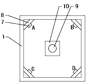
[0078] refer to figure 1 , the computer graphic information processing device 2 is a computer, images are stored in the computer graphic information processing device 2, the projector 3 is connected to the computer graphic information processing device 2 through a data line, and the stereoscopic imaging device is fixed on the scene box 4 top.

[0079] The stereoscopic imaging device comprises a projection screen 5 and a quadrangular pyramid 6, the projection curtain 5 is horizontally fixed above the mirror assembly, the quadrangular pyramid 6 is formed by splicing four pieces of isosceles triangular glass, and the quadrangular pyramid 6 is inverted on the projection surface. Above the screen 5 , the central axis of the quadrangular pyramid 6 is perpendicular to the projection screen 5 , and preferably the angle between the sides of the quadrangular pyramid 6 and the projection screen 5 is 45°. The projection screen 5 of the present invention can also be replaced by transparent...

Embodiment 2

[0107] The difference between this embodiment and Embodiment 1 lies in the method of cutting out the arrays a11, a21, a31 and a41 in the above step 202, and the method of combining a11, a21, a31 and a41 into the array a0.

[0108] The pixel size of the arrays a1, a2, a3, a4 is 640×480, and the pixel size of a0 is 640×640.

[0109] The specific steps of step 202 are as follows:

[0110] Step 20201, refer to Figure 13 , Extract the pixels from column e to column 640-e of row n in a1 Extract the pixels from column i+e to column 640-(i+e) of row n+i in a1, and in turn Execute until i+e=320 to get a11, i is an integer starting from 1, and e is any integer between 1 and 160;

[0111]Step 20202, rotate a2 clockwise by 90 degrees, extract the pixel points from row e to row 640-e of column 480-n in a2, and extract the pixels of row 480-(n+i+e) in column a2 Extract the pixels from line i+e to line 640-(i+e), and execute them sequentially until i+e=320, and get a21;

[0112] Step 20...

Embodiment 3

[0117] The above-mentioned embodiment 1 and embodiment 2 are for the case that the object to be imaged 9 is small in size and the image of the object to be imaged 9 can be contained in the array a11, when the array a11 of the isosceles right triangle cannot contain the image elements of the object to be imaged 9 , step 202 adopts the following method:

[0118] Cut out an array a11 containing the image of the object 9 to be imaged in a1. The upper part of the array a11 is a rectangle, and the lower part is an isosceles trapezoid with a wide top and a narrow bottom. The long horizontal side of the isosceles trapezoid is in line with the long side of the lower side of the rectangle Equal and coincident, the hypotenuse of the isosceles trapezoid is 45°, the upper long side of the rectangle is located at the nth row of a1 on the upper side of the image of the object 9 to be imaged, and the array a11 is also cut out in a2, a3 and a4 The arrays a21, a31, and a41 with the same shape a...


PUM


Abstract

The invention belongs to the technical field of three-dimensional display, and discloses a three-dimensional real-time phantom display system and a display method of the three-dimensional real-time phantom display system. The three-dimensional real-time phantom display system comprises an image acquisition box (1), a light module, an image acquisition device and a three-dimensional imaging device. An article (9) to be imaged is placed in the image acquisition box (1), and the light module is fixed in the image acquisition box (1) to provide lighting for the article (9) to be imaged. The image acquisition device comprises four cameras (7). A projector (3) is connected with the output port of a computer graphic information processing device (2), and the three-dimensional imaging device receives projections of the projector (3). The display method comprises the steps that the four cameras (7) extract four images of the article (9) to be imaged in four directions respectively; the four images are cropped through a LABVIEW to obtain four sub-images, and the four sub-images are spliced into a square combined image; the projector (3) projects the combined image onto the three-dimensional imaging device. The three-dimensional real-time phantom display system and the display method of the three-dimensional real-time phantom display system have the advantages that the article (9) to be imaged can be dynamically displayed in real time and can also be displayed in a magnified mode, and the structure is simple.

Description

technical field [0001] A phantom stereoscopic real-time display system and a display method thereof belong to the technical field of three-dimensional display. Background technique [0002] The existing phantom stereoscopic display system is to shoot the object to be imaged in advance, and then the captured picture is imaged on the stereoscopic imaging device after processing, which cannot display the object to be imaged in real time, which is inconvenient to use, and cannot achieve dynamic display of the object to be imaged Effect. The current stereoscopic display system directly projects the images collected in multiple directions of the object to be imaged onto the stereoscopic imaging device, and the stereoscopic image of the object to be imaged will be very small, which is not easy to observe, and the stereoscopic effect is not strong. Contents of the invention [0003] The technical problem to be solved by the present invention is to overcome the deficiencies of the...

Claims


Application Information

Patent Timeline
Patent Type & Authority Applications(China)
IPC IPC(8): G02B27/22G03B21/20
CPCG02B30/56G03B21/2033
Inventor 魏功祥党宝生姜清华
Owner SHANDONG UNIV OF TECH
Why Eureka
Try Eureka