Luminescent device and backlight source

A technology of light-emitting devices and light-emitting surfaces, applied in the directions of light sources, optical components, point light sources, etc., can solve the problems of bright spots on the display screen, uneven brightness of bright rings, and small light-emitting angles of light-emitting devices.

Inactive Publication Date: 2015-01-28
HISENSE VISUAL TECH CO LTD
View PDF5 Cites 10 Cited by
  • Summary
  • Abstract
  • Description
  • Claims
  • Application Information

AI Technical Summary

Problems solved by technology

[0005] Embodiments of the present invention provide a light-emitting device and a backlight, which solves the problems in the prior art that the light emitting angle of the light-emitting device is small, and when the light-emitting device is applied to a backlight, the brightness of the display screen is uneven such as bright spots and bright rings.

Method used


Image

  • Luminescent device and backlight source
  • Luminescent device and backlight source
  • Luminescent device and backlight source

Examples


Embodiment Construction

[0028] The following will clearly and completely describe the technical solutions in the embodiments of the present invention with reference to the accompanying drawings in the embodiments of the present invention. Obviously, the described embodiments are only some, not all, embodiments of the present invention. Based on the embodiments of the present invention, all other embodiments obtained by persons of ordinary skill in the art without making creative efforts belong to the protection scope of the present invention.

[0029] It should be noted that, in the embodiment of the present invention, the light incident surface of the optical lens means that the light enters the optical lens through this surface, and similarly, the light exit surface means that the light exits the optical lens through the surface.

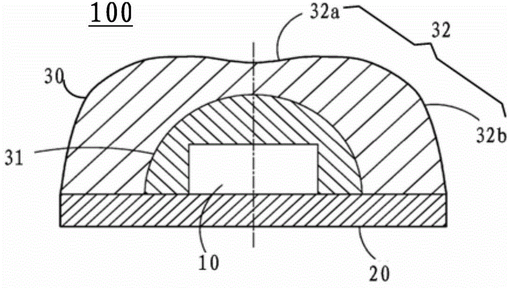
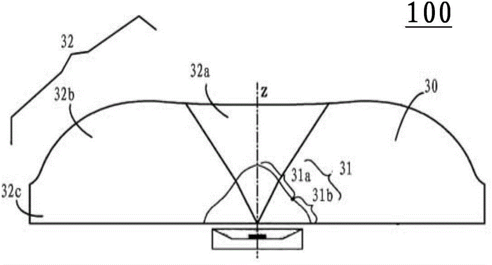
[0030] The embodiment of the present invention provides a light emitting device 100, such as Figure 5 As shown, the light-emitting device includes a light-emitting diod...


PUM


Abstract

The embodiment of the invention provides a luminescent device and a backlight source, relates to the technical field of display, and aims to solve the problems of small light emitting angle of a luminescent device and non-uniform brightness in application of the luminescent device to a backlight source display screen in the prior art. The luminescent device comprises a light emitting diode and an optical lens, wherein the optical lens comprises light incidence surfaces and light exit surfaces; the light incidence surfaces comprise a first light incidence surface and a second light incidence surface; the proportions of the smallest distance values of distances from all points on the first light incidence surface and the second light incidence surface to a central point of a luminescent surface to the biggest distance values belong to [0.5, 0.7] and [0.683, 0.695] respectively; the light exit surfaces comprise a first light exit surface and a second light exit surface; the proportions of the smallest values of distances from all points on the first light exit surface and the second light exit surface to the central point of the luminescent surface to the biggest distance values belong to [0.771, 0.913] and [0.883, 0.921] respectively.

Description

technical field [0001] The invention relates to the display field, in particular to a light emitting device and a backlight source. Background technique [0002] Liquid Crystal Displays (LCDs) have been widely used in electronic products with display functions such as mobile phones, computers, and televisions. As we all know, liquid crystal displays need a backlight source to achieve display. The light emitting diode (Light Emitting Diode, LED) has the characteristics of small size, low power consumption, long service life, wide color gamut, etc., and has become the mainstream light source of the backlight source of the liquid crystal display. However, due to the inherent disadvantages of light-emitting diodes such as small light-emitting angles and poor uniformity, the backlight source formed by using light-emitting diodes has problems such as uneven display brightness. [0003] In order to solve the inherent disadvantages of small light-emitting angle and poor uniformity...

Claims


Application Information

Patent Timeline
Patent Type & Authority Applications(China)
IPC IPC(8): G02F1/13357F21V5/04F21Y101/02
CPCG02F1/133603G02F1/133606G02F1/133607G02B19/0052F21V5/04
Inventor 李晓平钟强乔明胜
Owner HISENSE VISUAL TECH CO LTD
Why Eureka
Try Eureka