Shielding grounding spring, connector employing same, and connector assembly

A technology of shielding grounding and connectors, which is applied in the field of shielding grounding springs, can solve problems such as poor contact between shielding grounding springs and socket housings, failure of shielding grounding, and difficult positioning of shielding grounding springs, etc., to achieve good circumferential shielding effect, Fixed effect

Active Publication Date: 2015-01-28
CHINA AVIATION OPTICAL-ELECTRICAL TECH CO LTD
View PDF5 Cites 6 Cited by
  • Summary
  • Abstract
  • Description
  • Claims
  • Application Information

AI Technical Summary

Problems solved by technology

[0003] With the change of the use environment, more and more users require that the LRM connector can realize the requirements of sealing and circumferential shielding at the same time. Due to the small size of the LRM product, how to realize the complete sealing and better shielding of the product becomes a problem. A technical problem that is difficult to solve. When the existing shielding grounding spring is used, it is directly welded and fixed on the wall of the inner hole of the socket housing. This has the following problems. The shielding grounding spring is not easy to locate during the welding process. , due to the contact friction between the plug shell and the shielding ground spring, the welding point between the shielding ground spring and the socket shell is opened, and the shielding ground spring moves relative to the socket shell, which causes the shielding ground spring and the socket shell to not be well connected. contact, which may eventually cause the shield to ground to fail

Method used


Image

  • Shielding grounding spring, connector employing same, and connector assembly
  • Shielding grounding spring, connector employing same, and connector assembly
  • Shielding grounding spring, connector employing same, and connector assembly

Examples


Embodiment Construction

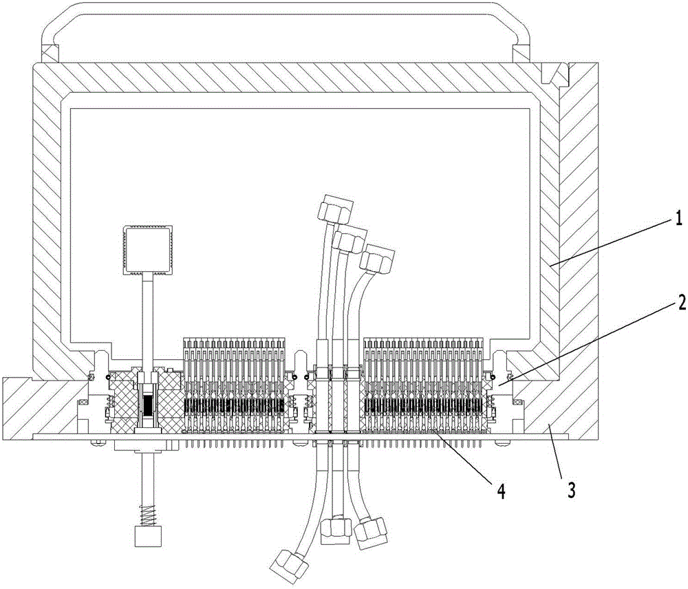
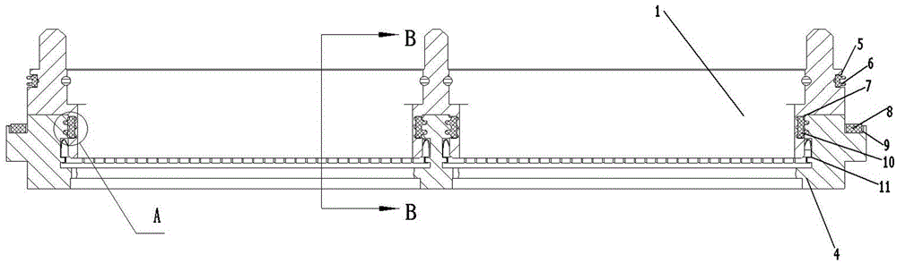
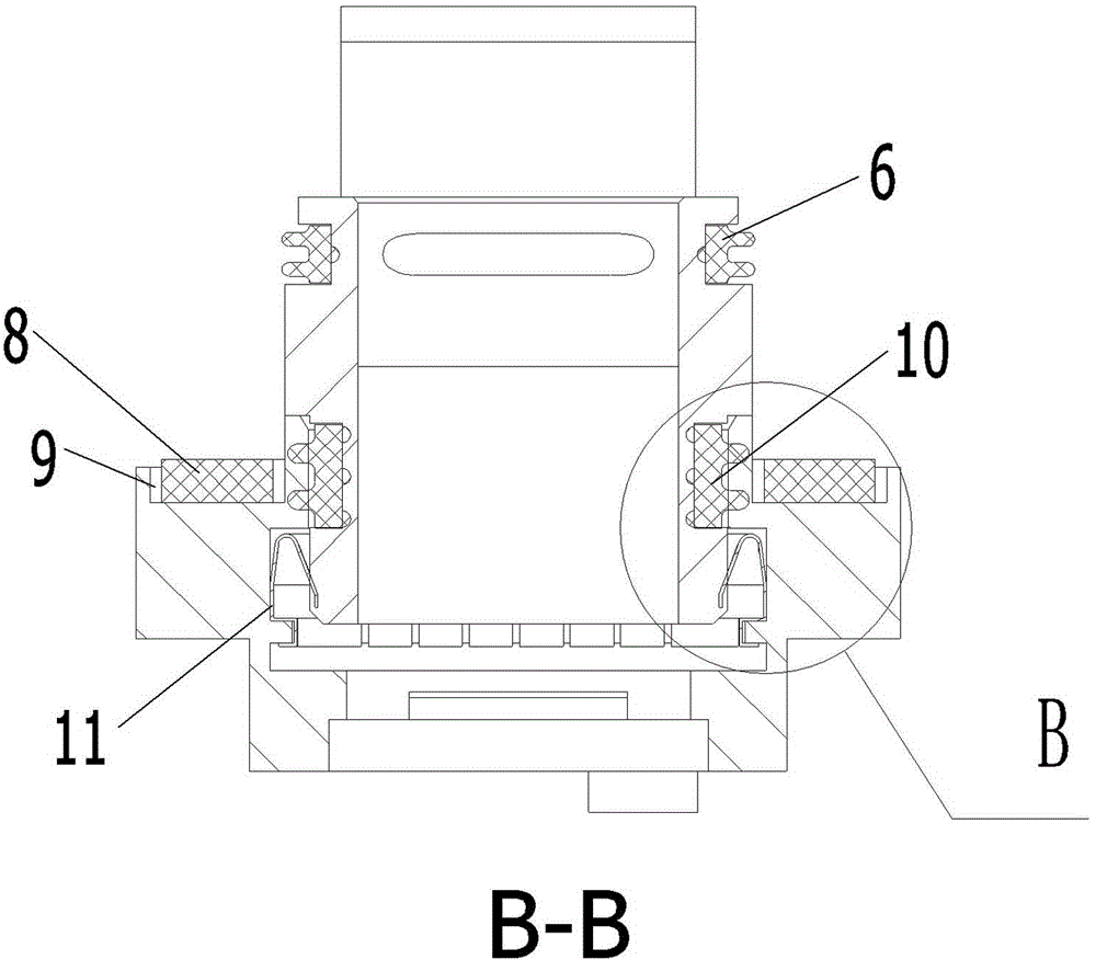
[0041] An example of a connector component is Figure 1~20Shown: This connector assembly is an LRM connector assembly, including a plug installation module 1, a plug 2, a socket 4 and a chassis panel 3, the plug includes a plug shell 13, and the socket includes a socket shell 12, and the plug and socket are connected in a rectangular shape Connectors, sockets and plugs are arc-adapted, so the socket can also be called a connector, and the plug is called a matching connector. A shielding grounding spring 11 is provided on the wall of the inner hole of the socket housing. The shielding grounding spring 11 includes an annular body 19. The annular body has an inner hole of the grounding spring for inserting the plug housing from front to back. The front end of the annular body is spaced along the circumferential direction. A plurality of reeds 17 cantilevered toward the center of the inner hole of the grounding spring are provided, and the reeds are located on the inner side of th...


PUM


Abstract

The invention relates to a shielding grounding spring, a connector employing the same, and a connector assembly. The shielding grounding spring comprises an annular body, and the annular body is provided with a grounding spring inner hole, wherein the grounding spring inner hole is used for the inserting of a housing of a corresponding adaptive connector from the front to the back. The annular body is provided with a plurality of spring pieces which are arranged along the peripheral direction at intervals, face the center of the grounding spring inner hole to extend in a suspension manner and are used for the sliding top-pressure cooperation with the housing of the adaptive connector. The annular body is provided with a plurality of U-shaped clamping pieces which are arranged at intervals along the peripheral direction. Each U-shaped clamping piece is provided with a clamping mouth which faces the direction departed from the center of the grounding spring inner hole. The invention also provides the shielding grounding spring which can be reliably fixed with the housing of the connector, the connector employing the shielding grounding spring, and the connector assembly.

Description

technical field [0001] The invention relates to a shielded ground spring, a connector and a connector assembly using the shielded ground spring. Background technique [0002] LRM is the acronym of Line Replaceable Module, which translates to field replaceable module or field replaceable module. The integrated transmission of various signals meets the functional requirements for reliable transmission of high-speed data and high-frequency data, and at the same time meets the functional requirements for power distribution between boards and sub-board systems. In order to meet the replaceable requirements, the LRM connector assembly includes a plug module housing, a plug connector, a socket connector and a chassis panel. The plug connector is installed on the plug module housing, and the socket connector is installed on the chassis panel. The plug includes a plug shell. Body, the socket includes a socket housing, and the plug housing is plugged into the inner hole of the socket...

Claims


Application Information

Patent Timeline
Patent Type & Authority Applications(China)
IPC IPC(8): H01R13/652H01R13/6584
CPCH01R13/5202H01R13/5219H01R13/652H01R13/6584
Inventor 郭建设
Owner CHINA AVIATION OPTICAL-ELECTRICAL TECH CO LTD
Why Eureka
Try Eureka