Road finishing machine

A road finishing machine and path technology, applied in road repair, road, road, etc., can solve the problems of low construction and maintenance costs, and achieve the effects of reducing maintenance costs, avoiding deposition, and increasing flow speed

Active Publication Date: 2015-01-28
ABG ALLG BAUMASCHINEN GMBH
View PDF9 Cites 2 Cited by
  • Summary
  • Abstract
  • Description
  • Claims
  • Application Information

AI Technical Summary

Problems solved by technology

[0006] Therefore, the technical problem to be solved by the present invention is to create a road finishing machine with a suction system for the harmful vapors generated when processing asphalt, the efficiency of which is to minimize the amount of steam, especially While increasing the amount of bitumen steam that could adversely affect the operator of the machine, construction and maintenance costs are low

Method used


Image

  • Road finishing machine
  • Road finishing machine
  • Road finishing machine

Examples


Embodiment Construction

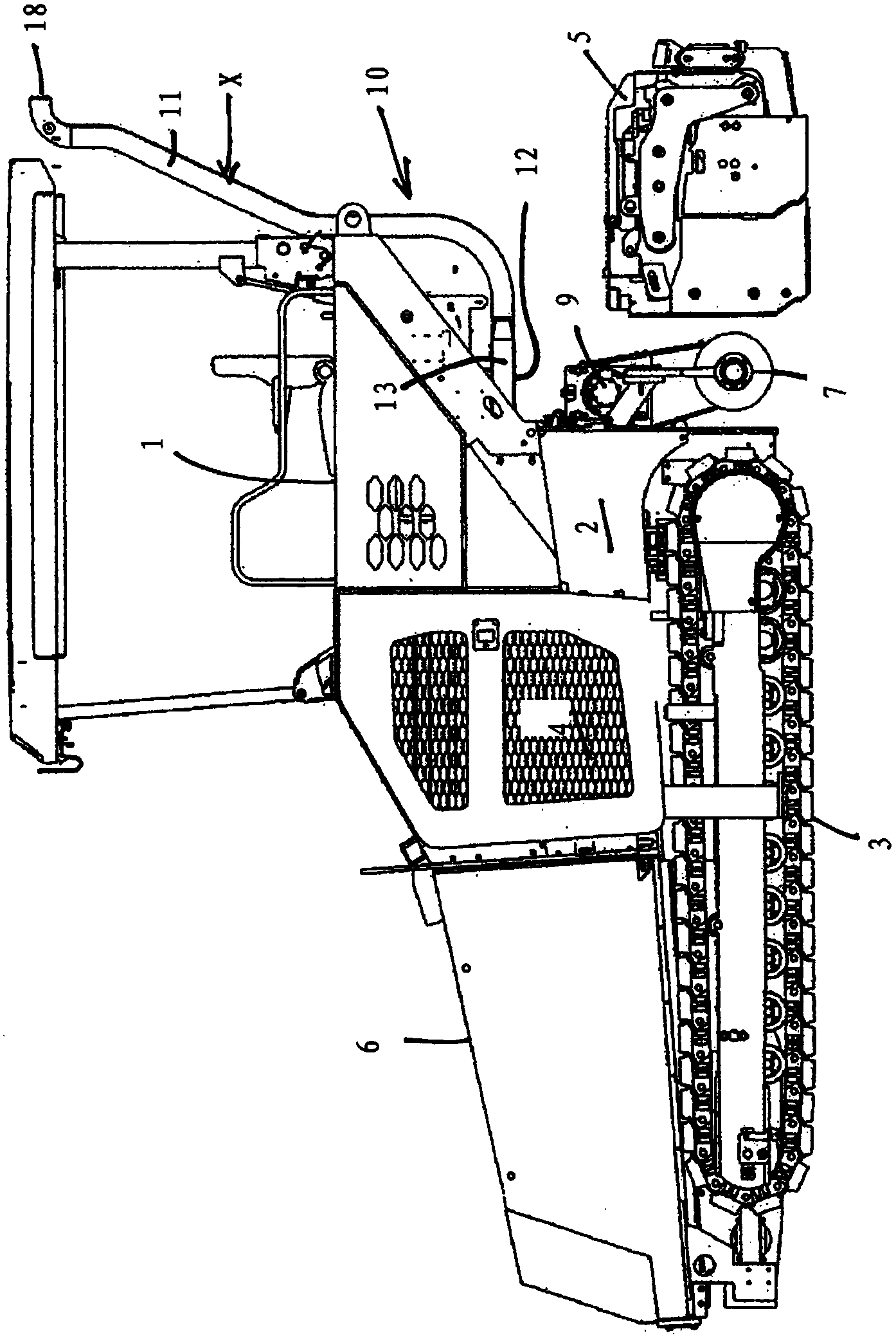
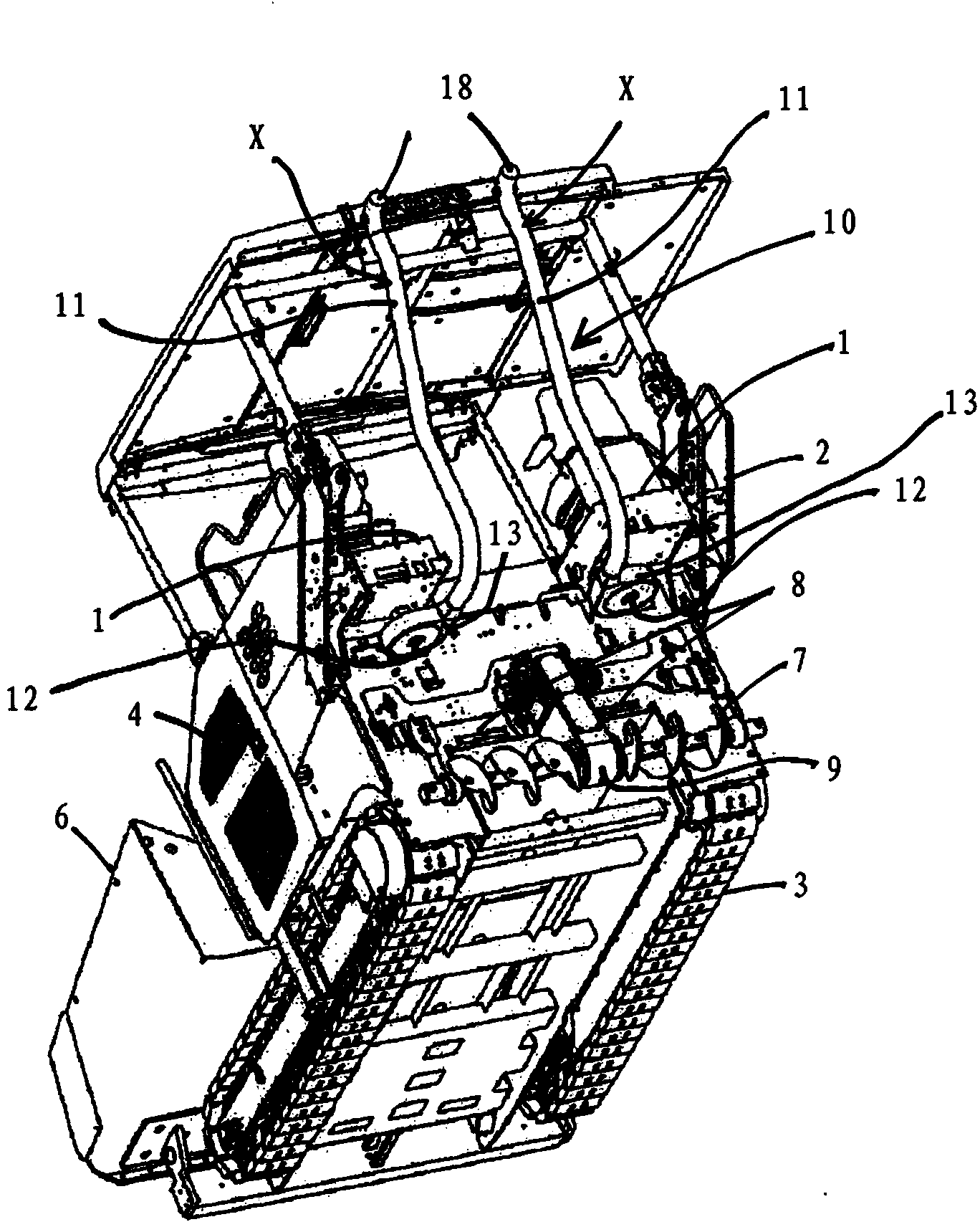
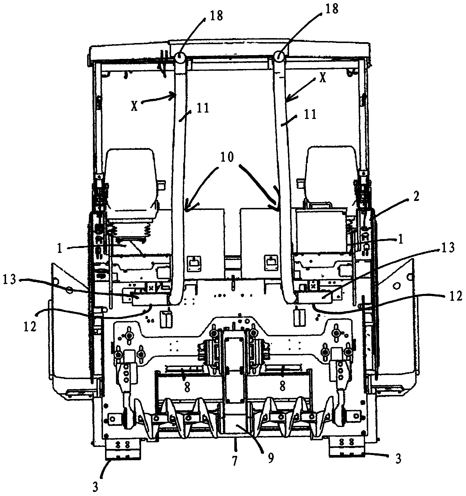
[0028] Figure 1 to Figure 3 Shown is a road finishing machine with a chassis 2 supporting a driver's platform 1, a running gear 3, at least one drive unit 4, a hydraulic system, a beam 5, an asphalt supply device comprising a storage hopper 6 and a secondary storage hopper 6 Longitudinal conveying device 8 for conveying to transverse distributor 7. This is a conventional configuration for road finishing machines. The running gear 3 is generally a crawler-type running gear, but it can also be a tire-type running gear or other running gears. The longitudinal conveying device 8 preferably comprises two conveyor belts running parallel in order to be able to feed the left and right parts of the transverse distributor separately. The transverse distributor 7 is preferably designed as a distributor screw with a preferably centrally arranged screw drive 9 .

[0029] The road finishing machine also comprises a steam extraction device 10 operated as a blower, which has at least one ...


PUM


Abstract

The invention relates to a road finishing machine comprising a chassis (2) supporting a driver's cab (1), an undercarriage (3), at least one drive unit (4), a hydraulic system, a screed (5), an asphalt supply arrangement comprising a supply hopper (6) and a longitudinal conveying device conveying from the supply hopper (6) to a cross-distributor (7), and a vapour extraction means (10) operated by a fan and comprising at least one airflow path (X), the extraction line (11) of which has a suction opening (12) above the cross-distributor (7) and an outlet opening (18) at a height above the driver's cab (1), wherein the fan (13) is arranged in the area of the suction opening (12) for the extraction line (11) in the at least one airflow path (X).

Description

technical field [0001] The invention relates to a road finisher according to the preamble of claim 1 . Background technique [0002] Road finishing machines are known from EP 0937182 B1 and US Pat. No. 5,938,371, which are equipped with a suction system for removing bitumen vapors based on bituminous materials. The main disadvantage that arises when bitumen is processed is that when bitumen is heated, the oily fractions in the bitumen tend to export relatively large amounts of hydrocarbons and additionally foul-smelling vapours. [0003] In order to remove the bitumen vapors from the road finisher, the known suction system has an air duct system with a longitudinally extending pipe part along which the bitumen is conveyed from the container in the road finisher The conveying device to the distributing screw extends so that along this conveying path and at its end the steam can be sucked into the cavity of the pipe part and discharged through the air outlet part. An air out...

Claims


Application Information

Patent Timeline
Patent Type & Authority Applications(China)
IPC IPC(8): B08B15/00E01C19/00E01C19/48
CPCE01C2301/50E01C19/48B08B15/00B60H1/24E01C19/002E01C19/12A63F9/0807A63F9/0857
Inventor H-J.科姆M.尼格曼
Owner ABG ALLG BAUMASCHINEN GMBH
Why Eureka
Try Eureka