Control device and control method for internal combustion engine

A control device and internal combustion engine technology, applied in engine control, internal combustion piston engine, electrical control, etc., can solve problems such as increased scavenging volume, increased overlap time, interference between intake valve and piston, etc.

Active Publication Date: 2016-02-24
NISSAN MOTOR CO LTD
View PDF6 Cites 0 Cited by
  • Summary
  • Abstract
  • Description
  • Claims
  • Application Information

AI Technical Summary

Problems solved by technology

[0004] However, in the above-mentioned Patent Document 1, in a state where the target compression ratio is high, when an attempt is made to increase the actual amount of intake air due to an increase in the required load, the valves of the intake valve and the exhaust valve are The increase of overlapping time cannot increase the amount of scavenging air and increase the actual amount of inhaled air
[0005] That is, when the target compression ratio is high, if the valve timing of the intake valve is changed to increase the actual amount of intake air so that the valve overlap time of the intake valve and exhaust valve increases, the intake valve There may be interference with the piston

Method used


Image

  • Control device and control method for internal combustion engine
  • Control device and control method for internal combustion engine
  • Control device and control method for internal combustion engine

Examples


Embodiment Construction

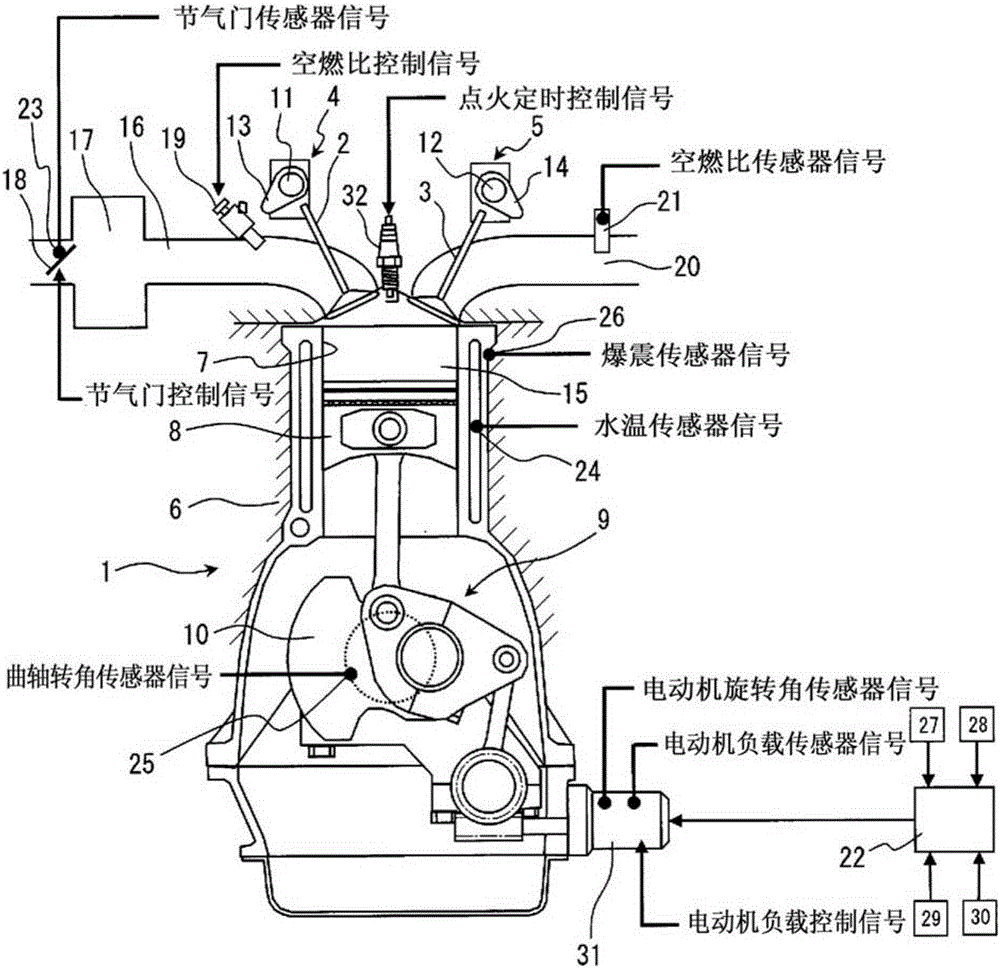
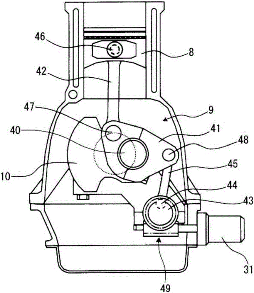
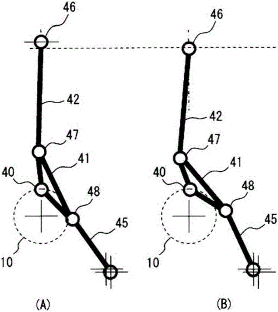
[0024] Hereinafter, an embodiment of the present invention will be described in detail based on the drawings. First, use figure 1 The basic structure of the internal combustion engine 1 to which the present invention is applied will be described. This internal combustion engine 1 is mounted on a vehicle as a drive source, and has: an intake valve side variable valve mechanism 4 capable of changing the valve timing of the intake valve 2; an exhaust valve side variable valve mechanism 5 capable of changing the exhaust the valve timing of the air valve 3; and the variable compression ratio mechanism 9 capable of changing the compression ratio of the internal combustion engine by changing the top dead center position of the piston 8 reciprocating in the cylinder block 7 of the cylinder block 6.

[0025] The variable valve mechanism 4 on the intake valve side and the variable valve mechanism 5 on the exhaust valve side are known phase variable mechanisms (VTC) disclosed in, for ex...


PUM


Abstract

In the condition that the valve overlap time of the intake valve (2) and the exhaust valve (3) is increased to increase the actual amount of intake air, by temporarily reducing the actual compression ratio to be lower than the target compression ratio in the steady state ( S24), so that the valve overlap time can be increased in such a way that the intake valve (2) and the exhaust valve (3) do not interfere with the piston (8).

Description

technical field [0001] The present invention relates to a control device and control method for an internal combustion engine, comprising: a variable valve mechanism capable of changing valve timing; and a variable compression ratio mechanism capable of changing the compression ratio by changing the top dead center position of a piston. Background technique [0002] There is known an internal combustion engine that includes: a variable compression ratio mechanism that changes the volume of a combustion chamber to change the compression ratio; and a variable valve mechanism that can change the valve timing of an intake valve or an exhaust valve. The internal combustion engine changes the compression ratio and the valve timing of the intake valve or the exhaust valve according to the operating state. [0003] For example, Patent Document 1 discloses a technique of setting the upper limit compression ratio so that the piston does not interfere with the intake valve whose outlet...

Claims


Application Information

Patent Timeline
Patent Type & Authority Patents(China)
IPC IPC(8): F02D15/02F02D13/02F02D43/00
CPCF02D13/02F02D15/02F02D41/0002F02D2041/001F02B75/048F02D41/10F02D41/006Y02T10/12Y02T10/40F02D13/0261F02D15/04
Inventor 釜田忍碇太介
Owner NISSAN MOTOR CO LTD
Why Eureka
Try Eureka