A spray device with a storage chamber

A technology of spraying device and spraying pipe, applied in spraying device, liquid spraying device, device for coating liquid on the surface, etc., can solve problems such as easy interruption of spraying distance, shortening, etc.

Active Publication Date: 2017-03-15
北京北机机电工业有限责任公司
View PDF7 Cites 0 Cited by
  • Summary
  • Abstract
  • Description
  • Claims
  • Application Information

AI Technical Summary

Problems solved by technology

[0003] The technical problem to be solved by the present invention is to overcome the disadvantages of the existing injection device that the flow is easily interrupted or the injection distance is shortened, and to provide a spray device with a storage chamber that has sufficient liquid flow during the injection so that the flow will not be interrupted.

Method used


Image

  • A spray device with a storage chamber
  • A spray device with a storage chamber

Examples


Embodiment Construction

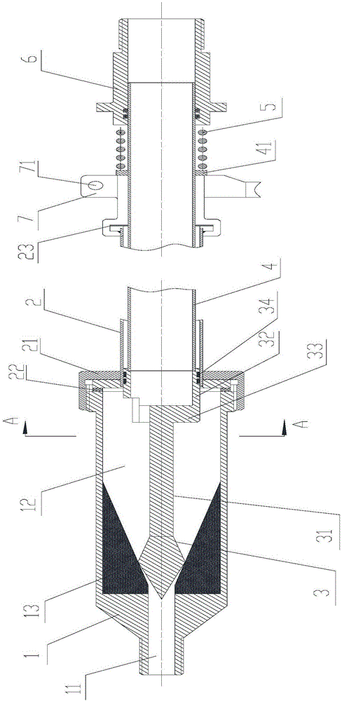
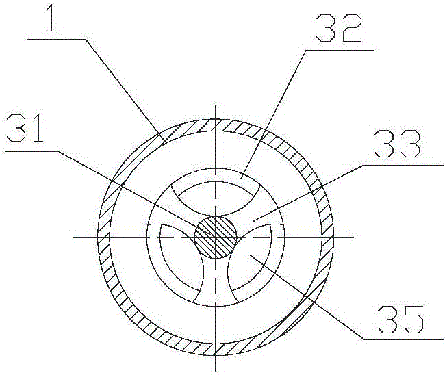
[0032] figure 1 A schematic structural view of an injection device with a storage chamber according to an embodiment of the present invention, as shown in figure 1 As shown, the injection device with a storage chamber of the present invention includes: a spray head 1 , a spray pipe 2 , a valve core 3 and an elastic member 5 . Wherein, the spray head 1 has a spray head cavity and a nozzle 11 communicating with the spray head cavity, and a valve seat 13 is provided on the inner wall of the spray head cavity. In this embodiment, the valve seat 13 is arranged at the position where the nozzle cavity and the nozzle 11 meet, so that the matching position of the valve core 3 and the valve seat 13 is also at the position where the nozzle cavity and the nozzle 11 meet, When the valve core 3 is disengaged from the valve seat 13, the liquid passes through the valve seat 13 and directly enters the spout 11 to be sprayed out. There is almost no loss of liquid pressure before being sprayed ...


PUM


Abstract

The invention discloses a jet device having a storage chamber. The jet device includes a nozzle, a jet pipe, a valve core and an elastic member. The nozzle is provided with a nozzle chamber and a nozzle mouth communicated therewith. A valve base is arranged on an internal wall of the nozzle chamber. A front end of the jet pipe is communicated with and sealedly connected to a back end of the nozzle, wherein the front end is towards to a jetting direction. A back end of a valve core body of the valve core is provided with two or more than two connecting wings which are vertical to an axial line of the valve core. Channels which allow liquid to enter into the nozzle chamber through the jet pipe are formed between the connecting wings. Under the situation that the valve core is matched with the valve base, the storage chamber is formed between the front ends of the connecting wings and the valve base. The size, in the axial line direction of the valve core, of the storage chamber is 1-3 times of an internal diameter of the nozzle chamber. The elastic member applies a force to a connecting pipe, wherein the force enables the connecting pipe to move towards the valve base. The jet device overcomes a defect that a jet device in the prior art is liable to cause flow breaking or reduction of a jet distance when the jet device in the prior art is used in point jet, especially for jetting a liquid in high viscosity. The invention provides the jet device having the storage chamber. By means of the jet device, a liquid flow is sufficient during point jet so that flow breaking is avoided.

Description

technical field [0001] The present invention relates to the field of liquid jetting. Specifically, it is an injection device with a storage chamber. Background technique [0002] Liquid injection is widely used in various fields. The injection device generally has a nozzle and a nozzle. The liquid enters the nozzle from the nozzle and sprays when the valve of the nozzle is opened. When spraying, continuous spraying is sometimes required, and burst injection is sometimes required. During continuous spraying, the liquid is continuously replenished to the nozzle under the action of hydraulic pressure. When spraying, especially when spraying oil with a high viscosity, the valve is in the open state for a short time, and the liquid in the nozzle has no time to replenish the nozzle, and the valve is closed. Since the liquid in the nozzle is not fully replenished, only a small amount of liquid can be ejected or the liquid cannot be ejected when spraying. Even if the liquid can b...

Claims


Application Information

Patent Timeline
Patent Type & Authority Patents(China)
IPC IPC(8): B05C5/02B05C11/10
CPCB05B9/04B05B12/002
Inventor 李振兴李喆李培培郭桂容陈伟
Owner 北京北机机电工业有限责任公司
Why Eureka
Try Eureka