Material grabbing hook type feeding mechanism

A technology of feeding mechanism and material hook, applied in metal processing equipment, feeding device, manufacturing tool, etc., can solve the problem of inconvenient to grab parts and so on

Inactive Publication Date: 2015-02-04
CHONGQING ZHIRUIDE TECH
View PDF1 Cites 6 Cited by
  • Summary
  • Abstract
  • Description
  • Claims
  • Application Information

AI Technical Summary

Problems solved by technology

However, during the process of grabbing parts, the feeding claws will slide with the slider, which is inconvenient to grab parts that are in a static state.

Method used


Image

  • Material grabbing hook type feeding mechanism

Examples


Embodiment Construction

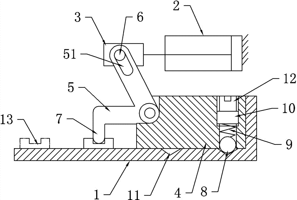
[0012] like figure 1 As shown, a material grabbing hook type feeding mechanism includes a cylinder 2, a machine base 1, a slider 4 and a swing rod 5, the slider 4 is slidingly matched with the machine base 1, wherein the swing rod 5 is in an "L" shape, and One end is provided with a catch hook 7 towards the outside of the swing rod 5, the other end of the swing rod 5 is provided with a strip hole 51, the piston rod of the cylinder 2 is provided with a connecting piece 3, and the connecting piece 3 is provided with a pin matching the strip hole 51 6. The corner of the pendulum 5 is hinged with the slider 4; the slider 4 is provided with a positioning structure, the positioning structure includes a compression spring 9 and a ball 8 connected to one end of the compression spring 9, the ball 8 protrudes from the bottom of the slider 4 and Contrasted with the machine base 1 , the machine base 1 is provided with two positioning grooves 11 arranged along the feeding direction and mat...


PUM


Abstract

The invention relates to a transportation or storage device, in particular to a material grabbing hook type feeding mechanism. The mechanism comprises an air cylinder, a machine seat, a sliding block and a swing rod, wherein the sliding block is in sliding fit with the machine seat; the swing rod is L-shaped; one end of the swing rod is provided with a material grabbing hook which faces the outer side of the swing rod; the other end of the swing rod is provided with a strip type hole; the piston rod of the air cylinder is provided with a connecting piece; a dowel matched with the strip type hole is arranged on the connecting piece; the corner part of the swing rod is hinged to the sliding block; a positioning structure is arranged in the sliding block; the positioning structure comprises a pressure spring and a rolling ball connected with one end of the pressure spring; the rolling ball stretches from the bottom part of the sliding block, and abuts against the machine seat; two positioning grooves formed along the material charging direction and matched with the rolling ball are formed in the machine seat. The material grabbing hook type feeding mechanism provided by the invention facilitates the grabbing for bowl-shaped parts in the static state.

Description

technical field [0001] The invention relates to a transport or storage device, in particular to a grabbing hook type feeding mechanism. Background technique [0002] In automatic production, there are often many mechanical parts, electronic components or raw materials that need to be processed automatically, such as punching and forming. At this time, the automation of the feeding mechanism becomes an important link. Therefore, the quality of the automatic feeding mechanism will directly affect the normal operation of the entire automated production system. [0003] There are many parts that are cold stamped into a bowl shape. After the parts are stamped and formed, they are sent to the designated position of the lathe for processing. At present, the commonly used feeding mechanism feeds the material by clamping. Since the parts are bowl-shaped and the walls of the parts are usually relatively thin, clamping the bowl-shaped parts is easy to cause deformation of the parts. ...

Claims


Application Information

Patent Timeline
Patent Type & Authority Applications(China)
IPC IPC(8): B21D43/04
CPCB21D43/04
Inventor 陈佳英
Owner CHONGQING ZHIRUIDE TECH
Why Eureka
Try Eureka