
A closed structure for the power room of a dual-fuel locomotive

A dual-fuel locomotive, closed structure technology, applied in locomotives, railway transportation, climate sustainability, etc., to achieve high safety effects

Active Publication Date: 2017-01-11
CRRC ZIYANG CO LTD
View PDF7 Cites 0 Cited by
  • Summary
  • Abstract
  • Description
  • Claims
  • Application Information

AI Technical Summary

Problems solved by technology

However, there is a hidden danger in the use of dual-fuel engines: once the liquefied natural gas pipe entering the upper part of the engine leaks, the leaked natural gas will become a flammable and explosive hazard in the power room, while ordinary diesel engines have no this problem

Method used


Image

  • A closed structure for the power room of a dual-fuel locomotive
  • A closed structure for the power room of a dual-fuel locomotive
  • A closed structure for the power room of a dual-fuel locomotive

Examples


Embodiment 1

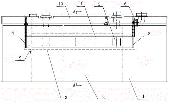
[0016] like figure 1 As shown, a closed structure of a dual-fuel locomotive power room includes a power room 1 and an engine 2 inside, the power room 1 seals the space above the engine 2 to form a closed room 3, and the top cover of the power room 1 is provided with a car body The ventilator 6 communicates with the interior of the closed chamber 3 , and the bottom of the closed chamber 3 is provided with an air inlet gap 10 , and the vehicle body ventilator 6 is arranged on the top cover of the front end of the power chamber 1 .

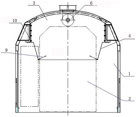
[0017] like image 3 As shown, the top of the power chamber 1 is provided with a fixed top cover 10, and the closed chamber 3 includes a rear end wall 7, a front end wall 8 and non-woven fabrics 4 on both sides, and the rear end wall 7, front end wall 8 and Non-woven fabric 4 is detachable design, and non-woven fabric 4 lower ends are connected on the engine 2 with bolts, and the upper end is connected with bolts on the fixed top cover 10.

[0018]...

Embodiment 2

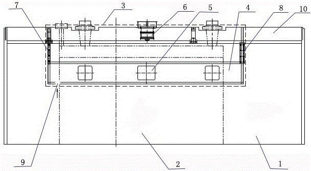
[0020] like figure 2 As shown, a closed structure of a dual-fuel locomotive power room includes a power room 1 and an engine 2 inside, the power room 1 seals the space above the engine 2 to form a closed room 3, and the top cover of the power room 1 is provided with a car body The ventilator 6 communicates with the interior of the closed chamber 3 , and the bottom of the closed chamber 3 is provided with an air inlet gap 9 , and the vehicle body ventilator 6 is arranged on the top cover of the middle part of the power chamber 1 .

[0021] like image 3 As shown, the top of the power chamber 1 is provided with a fixed top cover 10, and the closed chamber 3 includes a rear end wall 7, a front end wall 8 and non-woven fabrics 4 on both sides, and the rear end wall 7, front end wall 8 and Non-woven fabric 4 is detachable design, and non-woven fabric 4 lower ends are connected on the engine 2 with bolts, and the upper end is connected with bolts on the fixed top cover 10.

[002...


PUM


Abstract

The invention discloses a power chamber sealing structure of a dual-fuel locomotive. The power chamber sealing structure comprises a power chamber and an engine arranged in the power chamber, wherein the power chamber is used for sealing a space above the engine to form a sealed chamber; a locomotive body ventilator is arranged on a top cover of the power chamber and is communicated with the inner part of the sealed chamber; an air inlet gap is formed in the bottom of the sealed chamber. The power chamber sealing structure of the dual-fuel locomotive has the beneficial effects that liquefied natural gas which is likely to leak is effectively isolated in the sealed chamber and is pumped out of the power chamber in time, so that accidents can be prevented from occurring; and the safety is high.

Description

technical field [0001] The invention relates to the technical field of locomotives, in particular to a closed structure for a power chamber of a dual-fuel locomotive. Background technique [0002] Usually, the diesel locomotive engine is installed in the power room, and is exposed in the power room, so as to facilitate the maintenance of the engine. However, there is a hidden danger in the use of dual-fuel engines: once the liquefied natural gas pipe entering the upper part of the engine leaks, the leaked natural gas will become a flammable and explosive hazard in the power room, while ordinary diesel engines have no this problem. Therefore, it is necessary to improve the structure of the power room to improve safety and eliminate hidden dangers. Contents of the invention [0003] The object of the present invention is to provide a closed structure for the power chamber of a dual-fuel locomotive in view of the above existing problems. [0004] The technical scheme that ...

Claims


Application Information

Patent Timeline
Patent Type & Authority Patents(China)
IPC IPC(8): B61C17/06
CPCB61C17/06Y02T30/00
Inventor 栗韶毅吴振乾叶顶康朱延东卓文俊陈长明孟玉发黎焕先黄永
Owner CRRC ZIYANG CO LTD
Learn More