
Industrial quenching oil cooler

A cooler and quenching oil technology, which is applied to quenching devices, manufacturing tools, heat treatment equipment, etc., can solve the problems that cannot be disassembled and cleaned, easy to be blocked, etc., to achieve convenient disassembly and cleaning, reduce maintenance costs, and improve heat dissipation efficiency Effect

Inactive Publication Date: 2015-02-04
DCMC THERMAL TECH NINGGUO
View PDF5 Cites 0 Cited by
  • Summary
  • Abstract
  • Description
  • Claims
  • Application Information

AI Technical Summary

Problems solved by technology

The traditional industrial quenching oil cooler uses U-shaped welded pipes, which are easy to block during use; at the same time, it cannot be disassembled and cleaned because it is welded in one piece, and must be replaced if it is blocked.

Method used


Image

  • Industrial quenching oil cooler
  • Industrial quenching oil cooler
  • Industrial quenching oil cooler

Examples

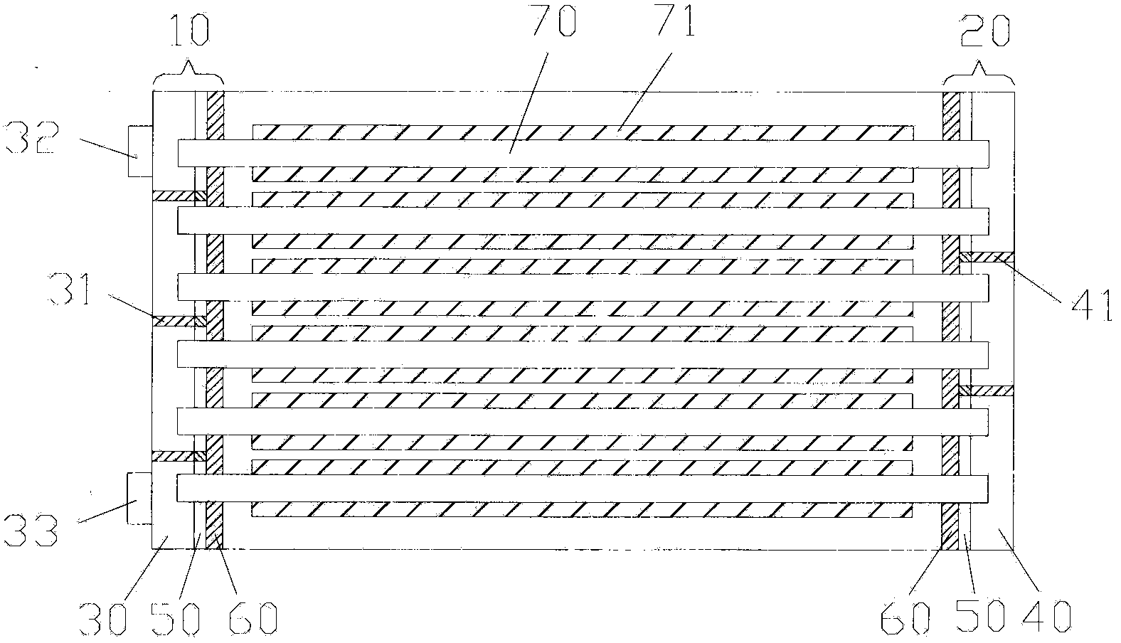
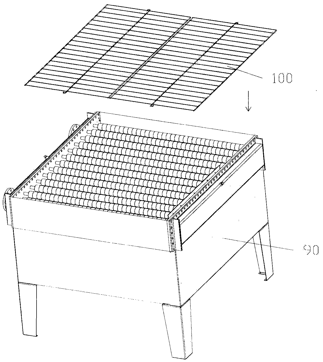
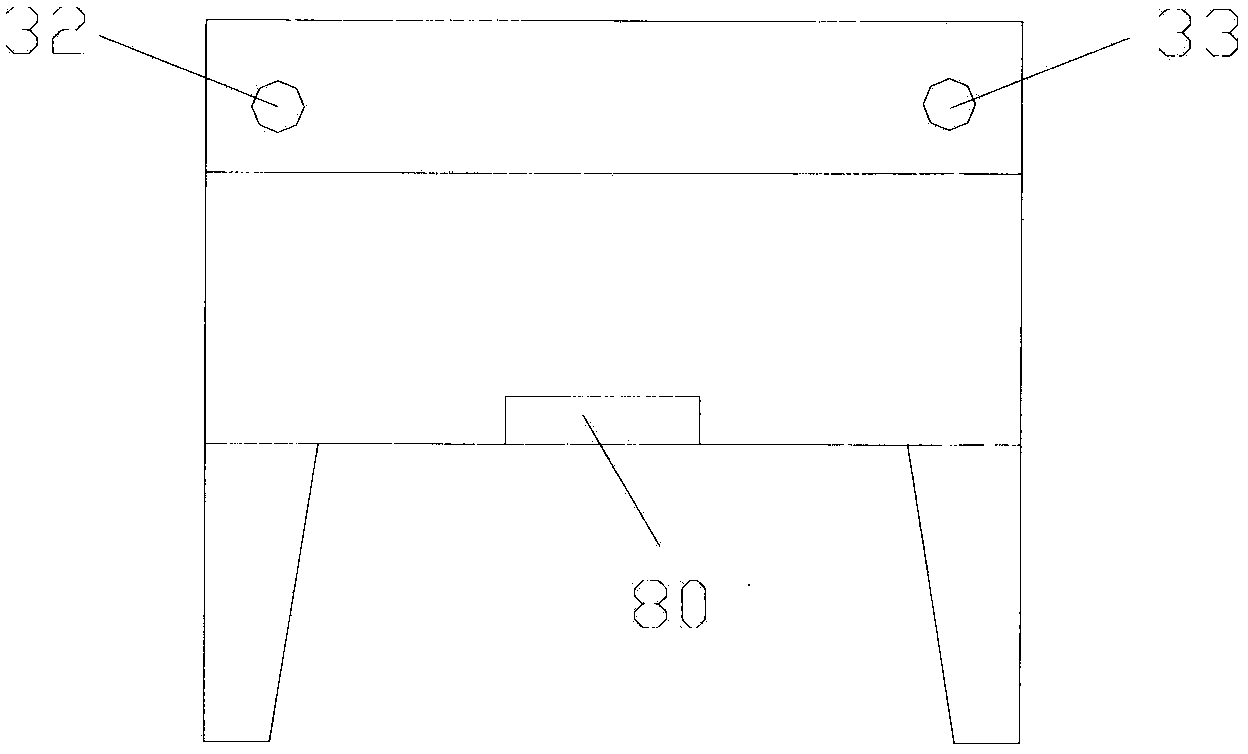

Embodiment Construction

[0024] combined with Figure 1-5 The technical scheme and structure of the technology of the present invention are described to facilitate the understanding of those skilled in the art.

[0025] An industrial quenching oil cooler, comprising several layers of radiating pipes 70 evenly arranged, each layer is provided with a plurality of, the lower end of the radiating pipes 70 is provided with a fan 80, and the two ends of the radiating pipes 70 are connected to the second oil chamber 20 and the device respectively. A first oil chamber 10 with an oil inlet 32 ​​and an oil outlet 33;

[0026] The first and second oil chambers 10 and 20 are provided with a plurality of splitter plates, which divide the oil outlets of the previous group of heat dissipation pipes 70 and the oil inlet ends of the rear group of heat dissipation pipes 70 into independent chambers to realize Quenching oil circulates along each group of cooling pipes 70 .

[0027] Preferably, the first oil chamber 10...


PUM


Abstract

The invention belongs to the technical field of heat dissipation and in particular designs an industrial quenching oil cooler. The industrial quenching oil cooler comprises a plurality of layers of uniformly distributed heat dissipation pipes, wherein a plurality of heat dissipation pipes are arranged in each layer; a fan is arranged at the lower end of each heat dissipation pipe; two ends of each heat dissipation pipe are respectively communicated with a second oil cavity and a first oil cavity which is provided with an oil inlet and an oil outlet; a plurality of shunting plates are arranged inside the first oil cavity and the second oil cavity; the oil outlet ends of a former group of heat dissipation pipes and the oil inlet ends of a later group of heat dissipation pipes are partitioned in independent chambers, so that the quenching oil can circularly flow along each group of heat dissipation pipes. Compared with the conventional industrial quenching oil cooler, the industrial quenching oil cooler has higher energy conservation and environmental protection effects and is convenient to disassemble and wash; the maintenance cost is reduced; the defect that the conventional industrial quenching oil cooler is easily blocked can be effectively solved.

Description

technical field [0001] The invention belongs to the technical field of heat dissipation and specifically designs an industrial quenching oil cooler. Background technique [0002] Industrial quenching oil cooler is a kind of oil cooling equipment commonly used in power system, and it is also suitable for metallurgy, chemical industry, mining, light industry and heavy industry and other departments. Traditional industrial quenching oil coolers use U-shaped welded pipes inside, which are easy to block during use; at the same time, because they are welded in one piece, they cannot be disassembled and cleaned. If there is blockage, it must be replaced. Contents of the invention [0003] The object of the present invention is to provide an industrial quenching oil cooler that is easy to disassemble and clean, has high cooling efficiency and is more environmentally friendly. [0004] In order to achieve the above object, the present invention provides the following technical sol...

Claims


Application Information

Patent Timeline
Patent Type & Authority Applications(China)
IPC IPC(8): C21D1/62
CPCC21D1/62
Inventor 布莱恩·罗素
Owner DCMC THERMAL TECH NINGGUO
Learn More