
Mobile backlight device

A backlight device and mobile board technology, applied in lighting devices, non-electric lighting devices, portable lighting devices, etc., to achieve the effect of ensuring lighting brightness

Inactive Publication Date: 2015-02-04
CHIZHOU YICHUANG ELECTRONICS TECH
View PDF0 Cites 6 Cited by
  • Summary
  • Abstract
  • Description
  • Claims
  • Application Information

AI Technical Summary

Problems solved by technology

[0003] The technical problem to be solved by the present invention is to provide a mobile backlight device to solve the existing shading problems

Method used


Image

  • Mobile backlight device
  • Mobile backlight device
  • Mobile backlight device

Examples


Embodiment Construction

[0026] In the following, numerous specific details are set forth in order to provide a thorough understanding of the concepts underlying the described embodiments. It will be apparent, however, to one skilled in the art that the described embodiments may be practiced without some or all of these specific details. In other instances, well known processing steps have not been described in detail.

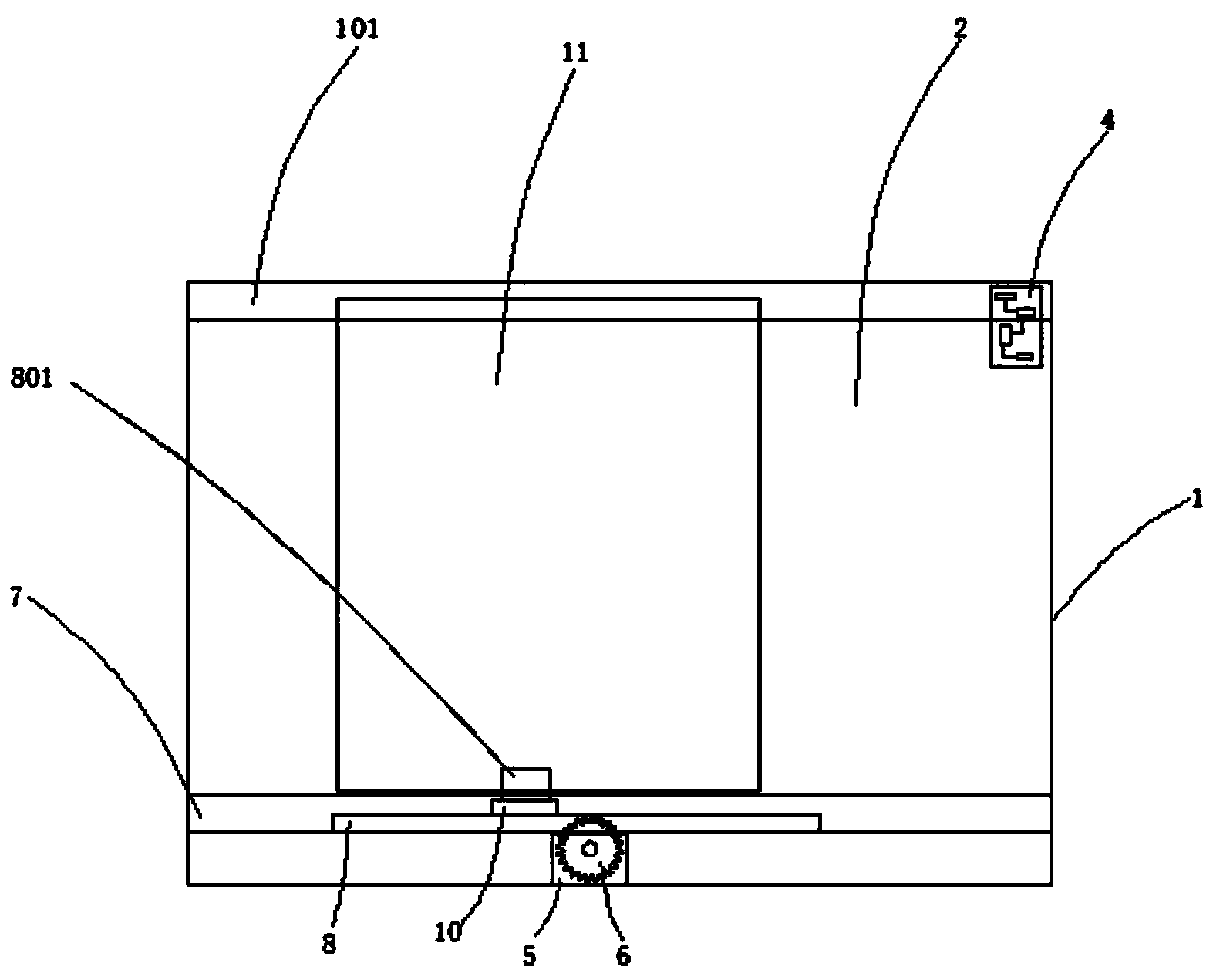
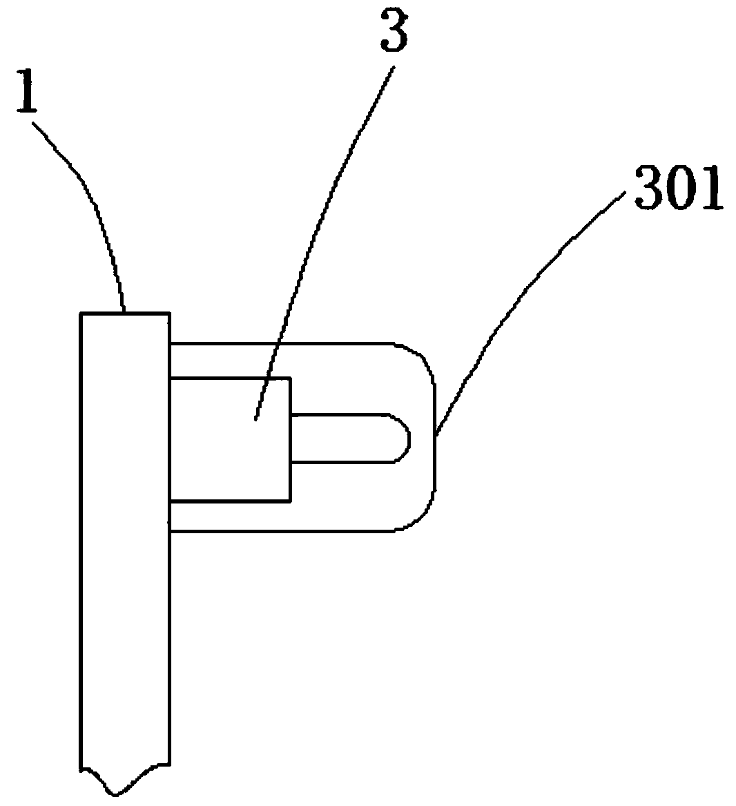
[0027] Such as figure 1 , figure 2 , image 3 , Figure 4 , Figure 5 , Figure 6 As shown, it includes frame 1, glass 2 installed inside the frame, including light controller 3, control terminal 4, stepper motor 5, gear 6, slide plate 7, rack 8, slider 9, moving plate 10, backlight plate 11. The light controller 3 is located on the right side of the outer upper end of the frame 1, and the two are glued together, the control terminal 4 is located on the upper right side of the inner frame 1, and the two are screwed together, and the stepping motor 5 is located on the The inner...


PUM


Abstract

The invention discloses a mobile backlight device. The mobile backlight device comprises a framework, glass arranged inside the framework, a brightness controller, a control terminal, a step motor, a gear, a sliding plate, a rack, sliding blocks, a mobile board and a backlight board, wherein the brightness controller is positioned on the right side of the upper end outside the framework and is connected with the framework through glue; the control terminal is positioned on the right side of the upper end in the framework and is connected with the framework through threads; the step motor is positioned at the bottom end in the framework and is connected with the framework through threads; the gear is positioned at the top end of the step motor and is closely matched and connected with the step motor; the sliding plate is positioned at the bottom end of the framework and is connected with the framework through threads; the rack is positioned in the sliding plate and is connected with the sliding plate in a sliding manner; the sliding blocks are positioned on two sides of the rack and are connected with the rack through welding; the sections of the sliding blocks are rectangular; the mobile board is positioned in the center of the top of the rack, and is connected with the rack through welding; the backlight board is positioned on the top of the mobile board, and is connected with the mobile board in a clamping manner. The device ensures normal work and life of indoor personnel and keeps out main light, and other scattered light still can enter a room through a gap of the backlight board to ensure illuminating brightness.

Description

technical field [0001] The invention relates to a glass, in particular to a mobile backlight device. Background technique [0002] With the acceleration of the pace of urban development, various buildings are also standing in various areas of the city. The outside of the buildings is generally equipped with glass. The glass is shot into the room, and the high-intensity bright light is shot into the room, which seriously affects people's work and life. Traditionally, sunshade curtains are used to block light, but this method will lead to insufficient indoor light, and the phenomenon of overcorrecting. In view of the above defects, it is necessary to design A mobile backlight device. Contents of the invention [0003] The technical problem to be solved by the present invention is to provide a mobile backlight device to solve the existing light-shielding problem. [0004] In order to solve the above technical problems, the technical solution of the present invention is: a m...

Claims


Application Information

Patent Timeline
Patent Type & Authority Applications(China)
IPC IPC(8): F21V1/08F21V14/08
CPCF21V1/08F21V14/08
Inventor 吉振
Owner CHIZHOU YICHUANG ELECTRONICS TECH
Learn More