An air swirling device arranged in the nozzle of a gas turbine combustor

A swirl device, gas turbine technology, applied in the direction of combustion chamber, continuous combustion chamber, combustion method, etc., can solve the problems of small air deflection angle, weak swirl strength, poor mixing effect of fuel and air, etc., and achieve wide design space, improved combustion reliability, and improved velocity distribution

Active Publication Date: 2017-11-03
CHINA UNITED GAS TURBINE TECH CO LTD
View PDF8 Cites 0 Cited by
  • Summary
  • Abstract
  • Description
  • Claims
  • Application Information

AI Technical Summary

Problems solved by technology

[0004] However, due to the gap at the bottom of the air swirl vane, the airflow deflection angle on the inner peripheral side of the channel is small, and the swirl strength is weak, which leads to poor mixing effect of fuel and air on this side, affecting the organization of combustion and the generation of pollutants

Method used


Image

  • An air swirling device arranged in the nozzle of a gas turbine combustor
  • An air swirling device arranged in the nozzle of a gas turbine combustor
  • An air swirling device arranged in the nozzle of a gas turbine combustor

Examples


Embodiment Construction

[0018] The principle, structure and specific implementation of the present invention will be further described below in conjunction with the accompanying drawings.

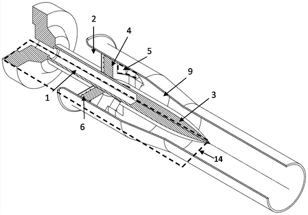
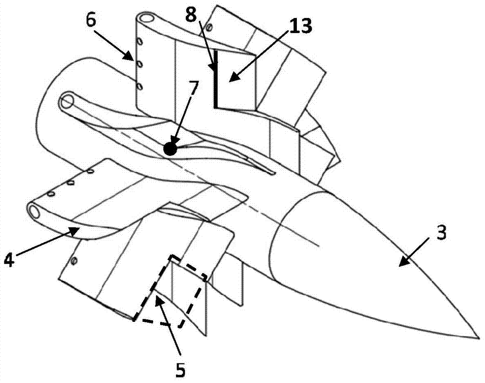
[0019] figure 1 , figure 2 and image 3 It is a schematic diagram of the structural principle of a gas turbine combustor nozzle equipped with an air swirl device. The air swirl device is arranged upstream of the central cone 3 in the peripheral annular air channel 2. The air swirl device 4 adopts an axial vane structure. It is best to adopt a hollow axial vane structure, which is evenly arranged along the peripheral annular air passage 2, and communicates with the central fuel passage 1 through the fuel injection hole 6, and the number of vanes is generally between 6 and 12.

[0020] The blade of the air swirl device 4 is provided with a notch 5, and the starting position is located at the bending angle change point 7 on the suction side of the blade. The intersection 8 of the cutting surface 13 of the notch 5 ...


PUM


Abstract

The utility model relates to an air swirl device arranged in a nozzle of a combustion chamber of a gas turbine, which belongs to the technical field of the gas turbine. The present invention includes a central fuel passage and a peripheral annular air passage. The peripheral axial annular air channel is arranged with a first-stage air swirl device in the axial direction outside the central cone. The blades of the air swirl device are provided with cutouts, and the starting position is located at the change point of the blade bending angle on the suction side of the blade. The intersection line of the cut surface and the blade suction side is perpendicular to the horizontal plane where the blade axis is located, and the direction of the cut surface is along the tangent direction of the bending angle change point of the blade suction side, and the length of the cut part runs through to the tail of the blade. The invention can ensure the swirl strength on the outer peripheral side of the air channel, increase the airflow velocity on the inner peripheral side of the air channel, match the nozzle outlet velocity distribution and the mixing effect of fuel and air, reasonably control the combustion area, and maintain the internal flow field structure of the combustion chamber. Thereby ensuring combustion stability and good outlet temperature distribution.

Description

technical field [0001] The invention relates to an air swirl device arranged in a gas turbine combustion chamber nozzle, in particular to a gas turbine low-pollution combustion chamber nozzle using natural gas fuel. Background technique [0002] In my country's current energy structure, thermal power generation using traditional coal-fired technology occupies the vast majority of the share. However, this traditional power generation technology has disadvantages such as low power generation efficiency, high pollutant emissions (especially NOx emissions), and high consumption of fresh water resources. As one of the clean energy technologies, the gas turbine power generation technology fueled by natural gas can effectively reduce pollutant emissions while meeting the power generation load requirements. Among them, the design of the gas turbine combustor nozzle is particularly important for organizing combustion and reducing pollutant emissions . [0003] In the combustion cha...

Claims


Application Information

Patent Timeline
Patent Type & Authority Patents(China)
IPC IPC(8): F23R3/14
Inventor 查筱晨张龙张珊珊刘小龙
Owner CHINA UNITED GAS TURBINE TECH CO LTD
Why Eureka
Try Eureka