Multipath laser beam automatic collimation device

A multi-channel laser and automatic collimation technology, applied in the direction of optics, optical components, instruments, etc., to reduce the difficulty of image processing, clear edges, and avoid engineering costs

Active Publication Date: 2015-02-04
NORTHWEST INST OF NUCLEAR TECH
View PDF3 Cites 8 Cited by
  • Summary
  • Abstract
  • Description
  • Claims
  • Application Information

AI Technical Summary

Problems solved by technology

[0006] The present invention proposes a multi-channel laser beam automatic collimation device for the multi-channel beams of the commonly used image transmission laser system. Far-field reference problem, and realize the integrated efficient automatic collimation of multiple laser beams

Method used


Image

  • Multipath laser beam automatic collimation device
  • Multipath laser beam automatic collimation device
  • Multipath laser beam automatic collimation device

Examples


Embodiment Construction

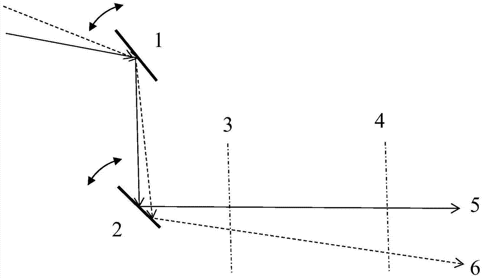
[0031] Below in conjunction with accompanying drawing, the alignment step of the present invention is further described:

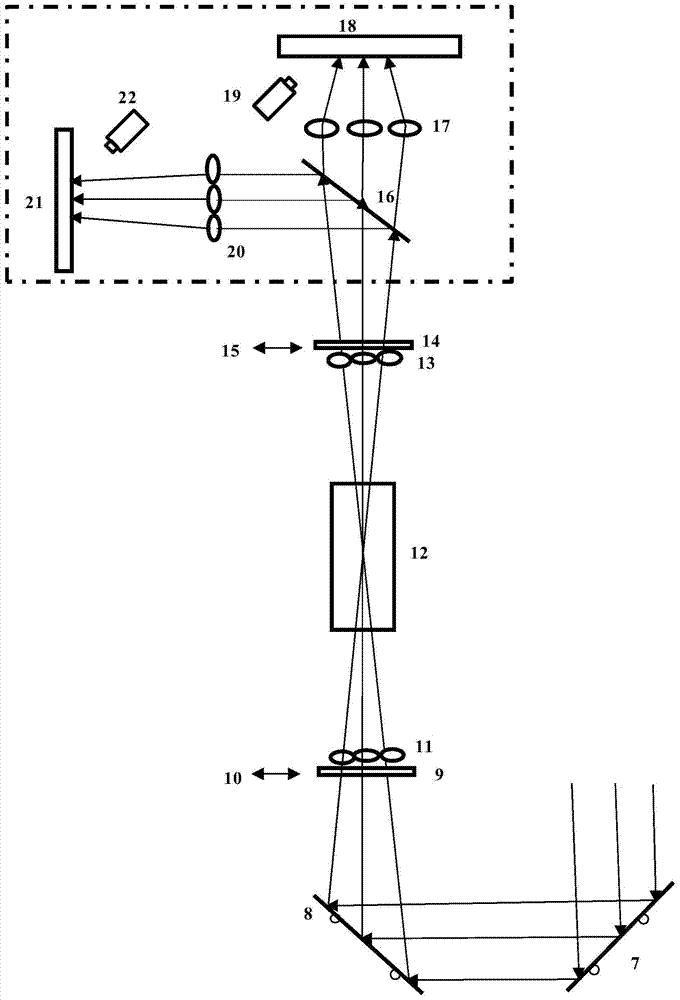
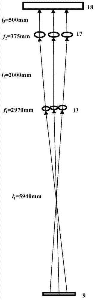
[0032] The automatic collimation of 18 beams of an excimer laser device is taken as an example for description. In order to achieve high-efficiency energy extraction of the amplifier, system output pulse width compression and beam smoothing on the target surface, the excimer laser system is designed to use 18 channels of narrow pulse width lasers to extract energy from the multi-stage amplifier according to the predetermined beam transmission path, and through image transfer The structure realizes multi-beam superposition and beam homogenization on the target surface. To simplify the description, the present invention takes 3 beams as an example for illustration.

[0033] The multi-channel laser beam automatic collimation system of the present invention is as figure 2 As shown, for the main optical path, the three input laser beams are transmitted to th...


PUM


Abstract

The invention discloses a multipath laser beam automatic collimation device. Multipath beam near-field and far-field reference synchronous images are transmitted to a photosensitive screen based on an image transmission automatic collimation structure of plug-in type fork wire arrays and fluorescence imaging by utilizing a double-cross fork wire array image transmission light path, and fluorescence imaging records of multiple beams generated by visible light CCD are utilized so that a problem of light path collimation near-field and far-field reference is solved, and integrated high-efficiency automatic collimation of multipath laser beams is also realized.

Description

technical field [0001] The invention relates to an automatic collimation method of multiple laser beams, in particular to a device suitable for real-time monitoring and automatic adjustment of multiple laser beams in a laser system. Background technique [0002] Large-scale high-power laser devices include a series of laser amplifiers and a large number of optical elements and components, with long optical paths and many links. The efficient operation of the system requires the configuration of the corresponding optical path automatic collimation system to quickly correct the deviation of the beam due to temperature changes, micro-vibration of the foundation and support frame, creep of the mechanical structure of the mirror, airflow and other random factors, and improve work efficiency. [0003] The so-called optical path collimation refers to the precise adjustment of the optical axis of the optical path after the optical system optical path has been established and the col...

Claims


Application Information

Patent Timeline
Patent Type & Authority Applications(China)
IPC IPC(8): G02B27/30
CPCG02B27/30
Inventor 王大辉钱航赵学庆马连英张永生邵碧波冯刚易爱平
Owner NORTHWEST INST OF NUCLEAR TECH
Why Eureka
Try Eureka