Transformer oil storage tank supporting structure

A transformer oil tank and support structure technology, applied in the direction of transformer/inductor cooling, etc., can solve the problem of long disassembly time, achieve the effects of improving efficiency, saving costs, and simplifying the support structure

Inactive Publication Date: 2015-02-04
CHONGQING WANGBIAN ELECTRIC GRP CORP
View PDF0 Cites 2 Cited by
  • Summary
  • Abstract
  • Description
  • Claims
  • Application Information

AI Technical Summary

Problems solved by technology

[0002] In order to meet the air insulation distance between the large transformer oil tank and the bushing, the transformer oil tank can be placed outside the end of the transformer oil tank. For this reason, the center of the transformer oil tank will deviate from the wall of the transformer oil tank, sometimes reaching 1m or even farther. Traditional transformers The outriggers of the oil tank are perpendicular to the bracket of the transformer oil tank and are relatively independent. The outriggers, the bracket and the transformer oil tank form a rectangle, and the outriggers of the transformer oil tank and the bracket of the transformer oil tank are fastened with a single row of bolts. The traditional support structure and the transformer are connected by bolts To connect, it is necessary to support the transformer oil tank part to screw the bolts during installation, and the bolt installation also makes the disassembly time longer

Method used


Image

  • Transformer oil storage tank supporting structure

Examples


Embodiment Construction

[0012] Below in conjunction with accompanying drawing and embodiment the technical solution of the present invention is further described:

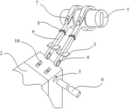
[0013] like figure 1 As shown, the supporting structure of the transformer oil storage tank includes a transformer oil tank 2, two ring clamps 7, a pillar 9 and a lock pillar 6; one end of the pillar 9 is connected to the ring clamp 7 through a flange 8, and the other end of the pillar 9 is provided with a fixed head , the fixed head is provided with a through hole 4 perpendicular to the axial direction of the pillar, and the inner wall of the through hole 4 is provided with a card edge. The transformer oil tank 2 is provided with a mounting hole 10 and a fixing hole 5 vertical to the mounting hole 10. It is also provided that the fixing head is inserted into the installation hole 10 correspondingly, and the fixing head is fixed in the installation hole 10 through the pillar 9 .

[0014] Pillar 9 is a hollow tube, used on the support of ...


PUM


Abstract

The invention relates to the field of a transformer auxiliary device, in particular to a transformer oil storage tank supporting structure. The transformer oil storage tank supporting structure comprises a transformer oil tank, two ring clamps, a support column and a lock column; one end of the support column is connected with the ring clamps through a flange, a fixed head is arranged on the other end of the support column, a through hole is respectively, axially and perpendicularly formed on the fixed head and the support column, a clamping rib is arranged on the inner wall of the through hole, the transformer oil tank is provided with an installation clamping hole and a fixed hole which is perpendicular to the installation clamping hole, a fixed hole is also arranged in the fixed hole and correspondently inserted into the installation clamping hole, and the fixed hole is fixed in the installation clamping hole by embedding the support column into the fixed hole. The transformer oil storage tank supporting structure has beneficial effects that by adopting the fixing way of the lock column and support column, the oil storage tank is convenient to install and dismount.

Description

technical field [0001] The invention belongs to the field of transformer auxiliary equipment, in particular to a supporting structure of a transformer oil storage tank. Background technique [0002] In order to meet the air insulation distance between the large transformer oil tank and the bushing, the transformer oil tank can be placed outside the end of the transformer oil tank. For this reason, the center of the transformer oil tank will deviate from the wall of the transformer oil tank, sometimes reaching 1m or even farther. Traditional transformers The outriggers of the oil tank are perpendicular to the bracket of the transformer oil tank and are relatively independent. The outriggers, the bracket and the transformer oil tank form a rectangle, and the outriggers of the transformer oil tank and the bracket of the transformer oil tank are fastened with a single row of bolts. The traditional support structure and the transformer are connected by bolts To connect, the trans...

Claims


Application Information

Patent Timeline
Patent Type & Authority Applications(China)
IPC IPC(8): H01F27/14
Inventor 程云怒
Owner CHONGQING WANGBIAN ELECTRIC GRP CORP
Why Eureka
Try Eureka