Head-up display

A head-up display and synthesizer technology, applied in the field of head-up displays, can solve problems such as inability to use sun visors and labor-intensive

Inactive Publication Date: 2015-02-04
PIONEER CORP
View PDF9 Cites 2 Cited by
  • Summary
  • Abstract
  • Description
  • Claims
  • Application Information

AI Technical Summary

Problems solved by technology

[0006] In the case of removing the sun visor installed on the vehicle and installing the head-up display, there is a problem that the installati...

Method used


Image

  • Head-up display
  • Head-up display
  • Head-up display

Examples


Embodiment

[0036] Hereinafter, preferred embodiments of the present invention will be described with reference to the drawings. In addition, "rotation" hereinafter also includes the case where the direction of conversion can be both clockwise and counterclockwise, and also includes the case where the movable range (angle) is limited.

no. 1 example

[0038] [Outline structure]

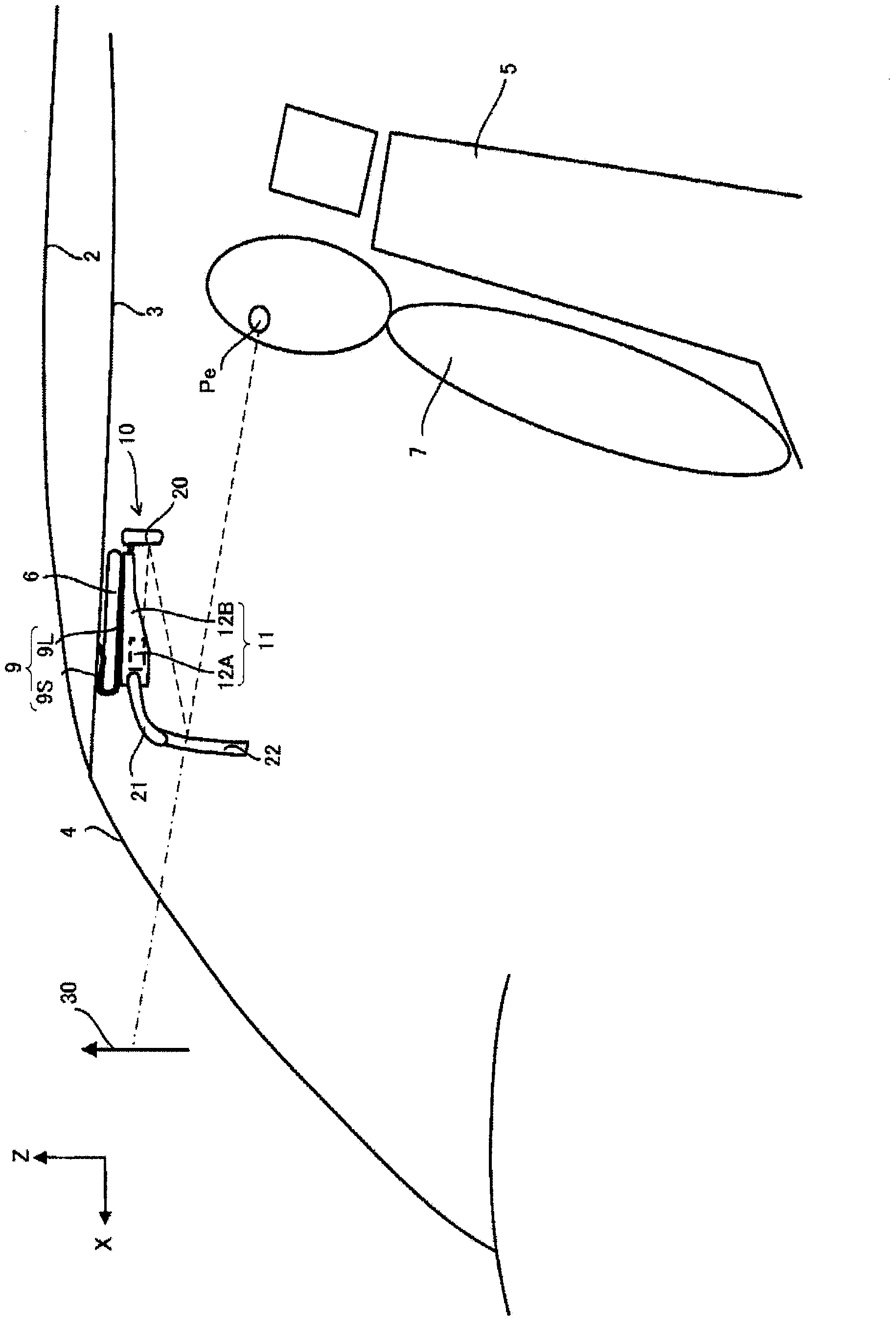
[0039] figure 1 A state in which the head-up display of the first embodiment is installed in the vehicle interior is schematically shown. figure 1 It is a figure which looked at the driver's seat of a vehicle from the side, and the driver 7 sits on the seat 5 in a vehicle interior. Above the head of the driver 7 is a roof (metal plate) 2 forming an outer frame of the vehicle, and a ceiling 3 serving as an interior of the vehicle compartment is provided below it. In addition, a windshield 4 and a sun visor 6 of the vehicle are located in front of the driver 7 . exist figure 1 Here, the sun visor 6 is fixed in a state facing the ceiling 3 (also referred to as a “storage state”). Hereinafter, let the width direction of the face of the sun visor 6 in the stored state and the ceiling 3 be the X-axis, the length direction be the Y-axis, and the direction perpendicular to the X-axis and the Y-axis be the Z-axis, and the positive direction of each axis...

no. 2 example

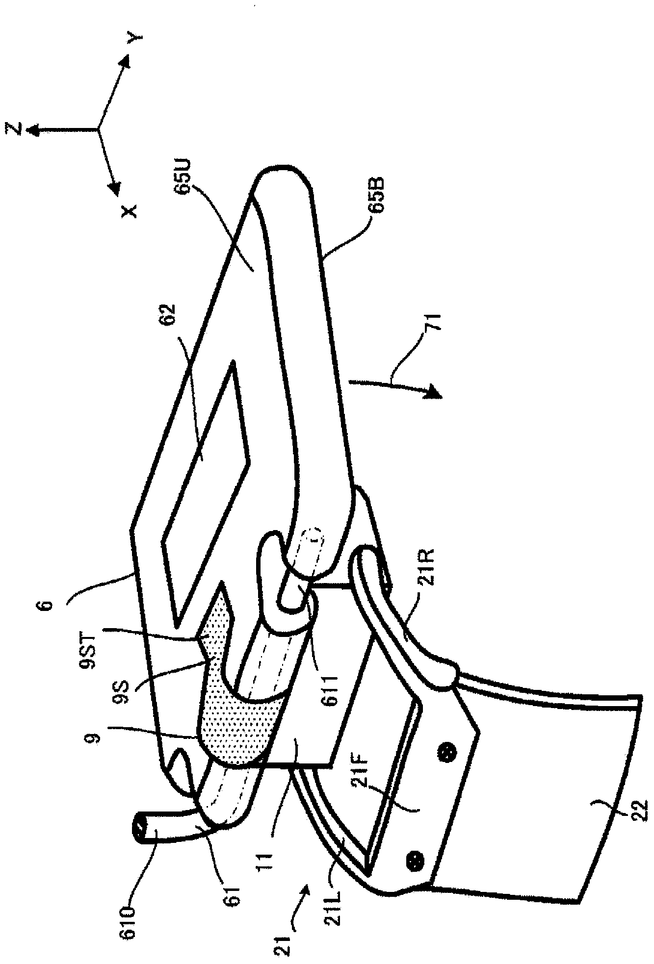
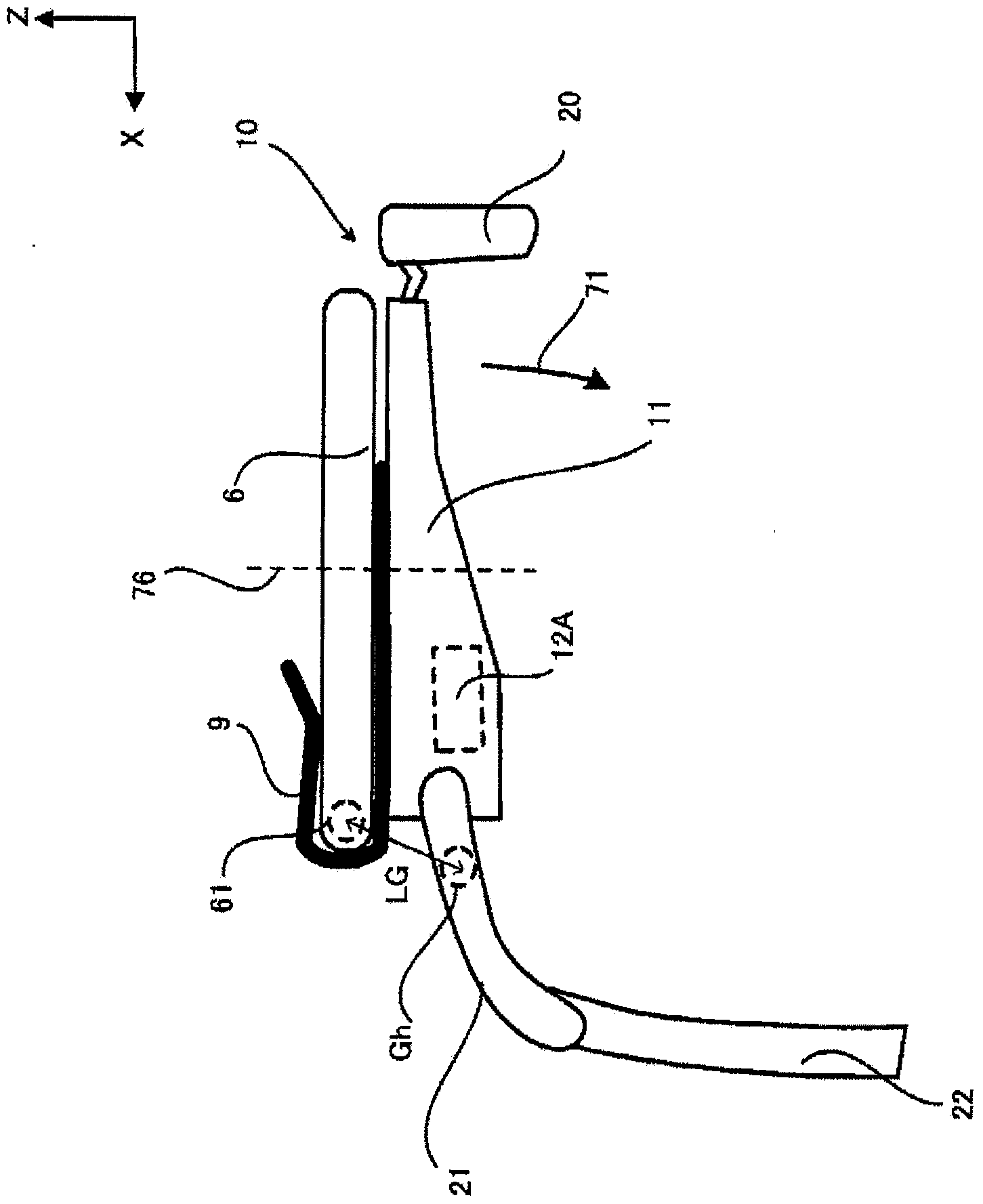
[0060] The head-up display of the second embodiment differs from the first embodiment in that the reflector 20 and the combiner 22 are foldable so as to face the sun visor 6 , respectively, in addition to the structure of the first embodiment. Other structures that are the same as those in the first embodiment use the same reference numerals, and their descriptions are appropriately omitted.

[0061] Figure 4 (A) is a figure which looked at the head-up display attached to the sun visor 6 from the Y-axis positive direction side. Such as Figure 4 As shown in (A), the support portion 21 is rotatable in the arrow 72 direction and its opposite direction about the ends 21T rotatably mounted on both sides substantially perpendicular to the Y-axis direction of the light source unit 11 as axes. The reflection part 20 is supported by the support part 23 provided in the light source unit 11 . Then, when a predetermined pressure or more is applied to the reflector 20 in the direction...


PUM


Abstract

This head-up display is provided with a main body section and an attachment means. The main body section displays a virtual image in a manner so as to overlap the anterior scenery. The attachment means attaches the main body section to a sun visor provided to the anterior ceiling portion of a vehicle. Also, the attachment means is configured in a manner so that when the main body section is attached to the sun visor, the center of gravity of the main body section is positioned in the vicinity of the sun visor support shaft.

Description

technical field [0001] The present invention relates to a technology of a head-up display mounted on a vehicle. Background technique [0002] Conventionally, there is a technology of a head-up display in which an image representing information related to vehicle driving is visually recognized as a virtual image based on the driver's eye position (eye point). For example, Patent Document 1 discloses a head-up display in which a combiner and a light source unit are integrally formed and mounted on a roof portion of a vehicle instead of a sun visor. In addition, Patent Document 2 discloses the use of a sun visor processed for attachment of a head-up display. [0003] Patent Document 1: Japanese Unexamined Patent Publication No. 2012-071825 [0004] Patent Document 2: Japanese Unexamined Patent Publication No. 2007-290484 Contents of the invention [0005] The problem to be solved by the invention [0006] When installing the head-up display by removing the sun visor provi...

Claims


Application Information

Patent Timeline
IPC IPC(8): B60K35/00
CPCB60K35/00B60K2370/1529B60K2370/67B60K2370/771B60K2370/81
Inventor 白山光祐佐佐木智子桥田雅也小林孝史新饲康广
Owner PIONEER CORP
Why Eureka
Try Eureka