Drivers for Capacitive Loads

A technology of capacitors and drivers, applied in the direction of using vibrating fluids, generators/motors, piezoelectric effects/electrostrictive or magnetostrictive motors, etc., can solve problems such as expensive technology

Active Publication Date: 2018-07-10
TEXAS INSTR INC
View PDF10 Cites 2 Cited by
  • Summary
  • Abstract
  • Description
  • Claims
  • Application Information

AI Technical Summary

Problems solved by technology

This particular technique is often prohibitively expensive due to the use of multiple large and expensive components such as multiple inductors

Method used


Image

  • Drivers for Capacitive Loads
  • Drivers for Capacitive Loads
  • Drivers for Capacitive Loads

Examples


Embodiment Construction

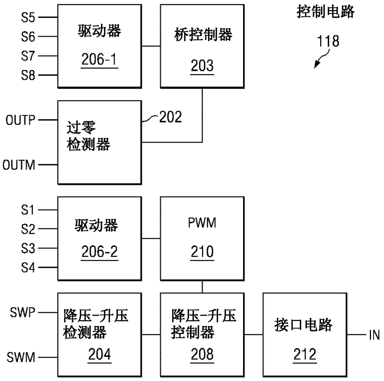
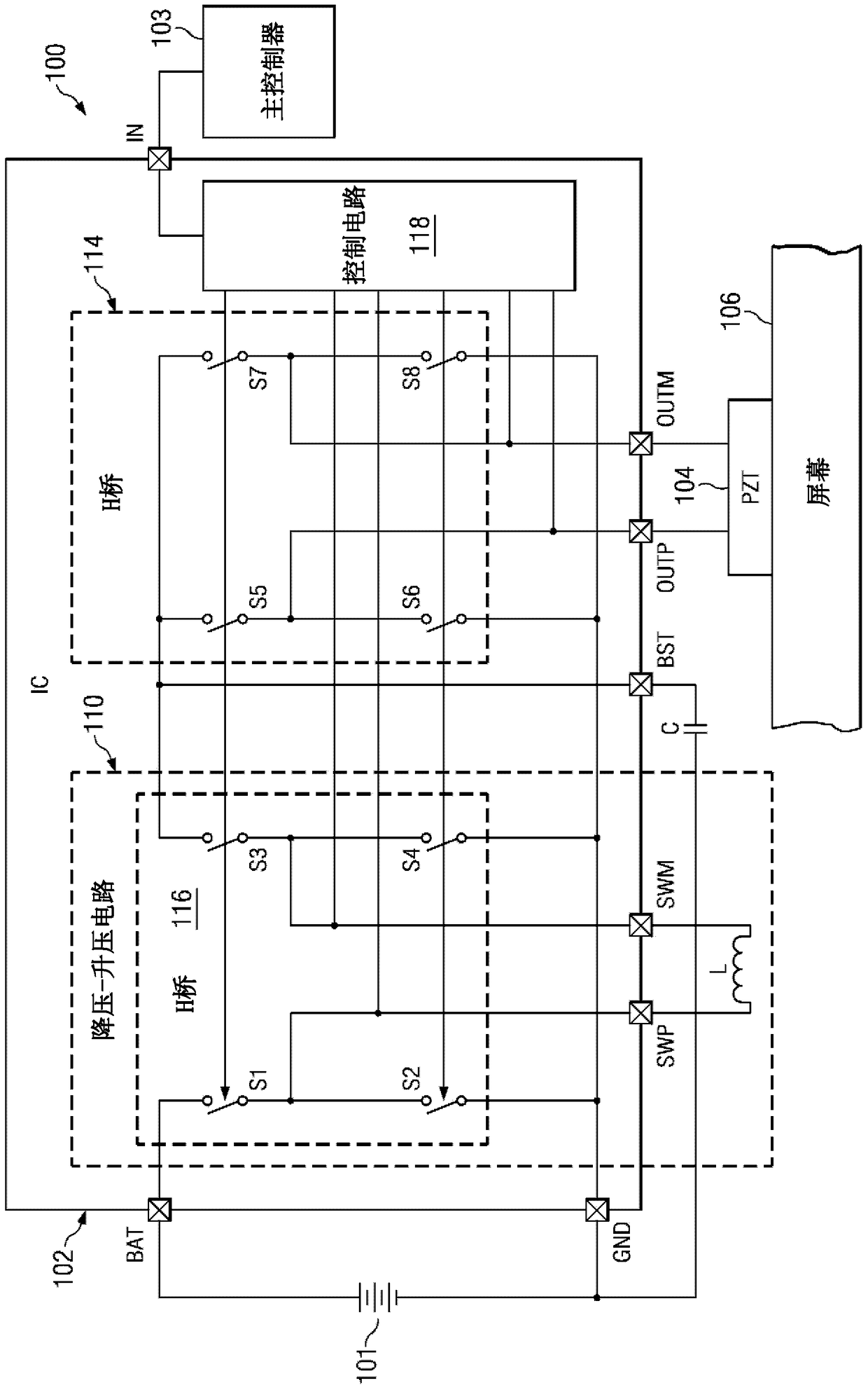
[0035] figure 2 and 3 An example of system 100 is shown. In this example, the system 100 may be a mobile device (e.g., a mobile phone) having a main processor 103 that can provide signals to an integrated circuit (IC) 102, which typically acts as a piezoelectric transducer or PZT 104 piezoelectric actuators. Based on an input signal (received via pin or terminal IN), control circuit 118 may provide control signals to switches S5 through S8 of H-bridge 114 and switches S1 through S4 of H-bridge 116, respectively, causing PZT 104 to vibrate screen 106 or the chassis of a mobile device (eg, a mobile phone) to generate audio signals or haptic effects. IC 102 is thus capable of driving PZT 104 substantially throughout the audio frequency band (eg, between about 50 Hz and about 20 kHz).

[0036] Generally, in operation, the H-bridge 116 is responsible for "driving" the PZT 104 by providing the appropriate power and frequency. Such as figure 2As shown in the example in FIG. 1 ,...


PUM


Abstract

The present invention provides a device (100) and method for driving a piezoelectric transducer (PZT). The H-bridge (116) includes switches (S1-S4), and the H-bridge (116) is coupled to the inductor L through terminals SWP and SWM and it functions as a buck-boost circuit (110). The control circuit (118) receives a control signal from the main processor (103) indicating the desired power output and frequency of PZT recovery (104). Based on current and / or voltage sensing from the buck-boost circuit terminals (SWP, SWM, BST), the control circuit (118) generates a pulse width modulated (PWM) signal, which is used to control the switches (S1- S4) Thus enabling the buck-boost circuit (110) to provide the charge on capacitor C from the battery (101) coupled to the H-bridge (116) at the appropriate time.

Description

technical field [0001] The present invention relates generally to drivers for capacitive loads, and more particularly to drivers configured to drive piezoelectric transducers in the audio frequency band. Background technique [0002] In many applications, increased robustness and reduced cost are desired. One application with this desire is mobile space devices, this approach is twofold, reducing cost and increasing robustness, that is, changing the human-machine interaction part of mobile devices by separating speaker and haptic functions. To achieve this goal, piezoelectric transducers can be affixed to the screen to vibrate the screen, allowing the screen to act as a speaker or a touchscreen with tactile feedback (eg, vibration feedback indicating a key touch). [0003] One problem, however, is that piezoelectric transducers are typically high capacitive loads (eg, 1 μF) and it is difficult to drive these transducers with sufficient mass to act as speakers and with suffi...

Claims


Application Information

Patent Timeline
Patent Type & Authority Patents(China)
IPC IPC(8): H02N2/06
CPCH02M3/1582B06B1/0238H10N30/802
Inventor M·加格D·J·白德文B·肖
Owner TEXAS INSTR INC
Why Eureka
Try Eureka