
X-ray unit with slit aperture

A technology of X-ray and aperture, applied in the field of X-ray unit, achieves the effect of low cost, simple technology and easy realization

Active Publication Date: 2017-07-28
SIEMENS HEALTHCARE GMBH
View PDF1 Cites 0 Cited by
  • Summary
  • Abstract
  • Description
  • Claims
  • Application Information

AI Technical Summary

Problems solved by technology

The problem gets worse as the width or number of rows of modern X-ray detectors increases

Method used


Image

  • X-ray unit with slit aperture
  • X-ray unit with slit aperture
  • X-ray unit with slit aperture

Examples


Embodiment Construction

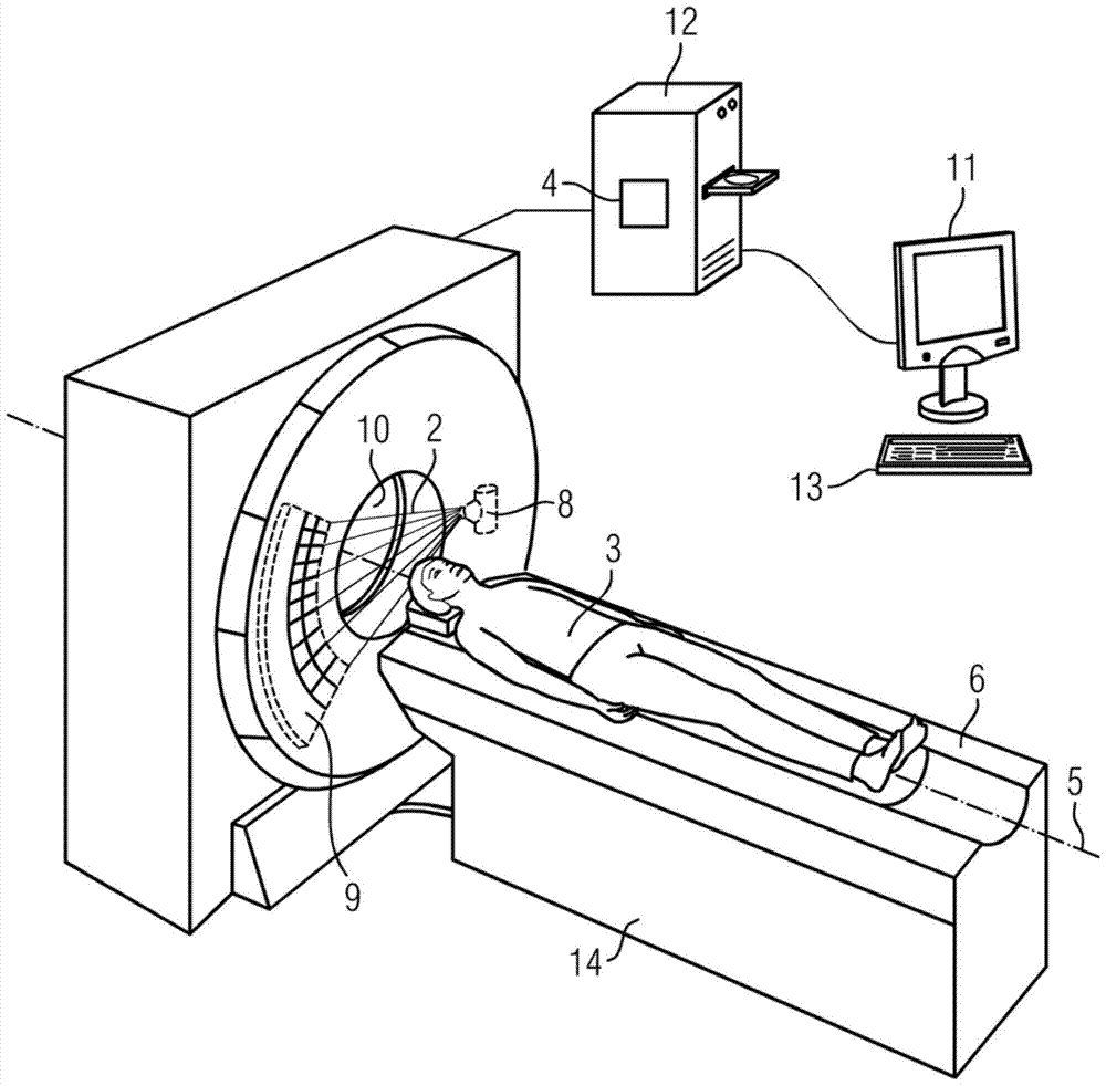
[0021] figure 1 An x-ray unit according to the invention in the form of a computed tomography machine is shown, which has a recording unit comprising an x-ray emitter 8 and an x-ray detector 9 . The recording unit rotates about the longitudinal axis 5 during recording of the X-ray projections, and the X-ray emitter 8 emits X-rays in the form of an X-ray beam during recording. In particular, the x-ray beam can be fan-shaped or cone-shaped. A computed tomography apparatus can also have more than just one x-ray emitter 8 and more than just one x-ray detector 9 in order to enable recording according to the so-called dual-energy method. In the example shown here, the x-ray emitter 8 is an x-ray tube. In the example shown here, the x-ray detector 9 is a line detector with a plurality of lines, for example with 128 lines or with 256 lines. However, the x-ray detector 9 can also be designed as a planar detector. The x-ray detector 9 is generally designed as a scintillation counter...


PUM


Abstract

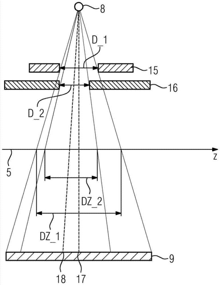
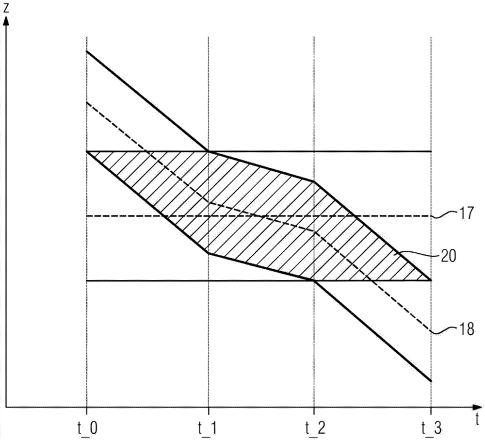
The invention comprises an x-ray unit and a method for recording x-ray projections. The x-ray unit according to the invention is designed for moving the examination object along the longitudinal axis at a feed speed and further comprises a recording unit which is rotatable about the longitudinal axis. The recording unit includes an X-ray emitter for emitting X-rays in the form of X-ray beams and an X-ray detector for detecting X-rays. The inventors realized that a fixedly positioned first slit aperture having a first opening of width D_1 along the longitudinal axis designed for shaping an X-ray beam having a width DZ_1 at the level of the longitudinal axis and having a first aperture along the longitudinal axis A second slit aperture with a second opening of width D_2 on the longitudinal axis, designed for shaping an x-ray beam with width DZ_2 at the level of the longitudinal axis, is sufficient to enable selective irradiation of the active volume in helical mode, wherein There is DZ_2

Description

technical field [0001] The invention relates to an x-ray unit and a method for recording x-ray projections. Background technique [0002] Computed tomography is an imaging method that is mainly used in medical diagnosis and for material inspection. To record tomographic x-ray images, the x-ray emitter and the cooperating x-ray detector are rotated around the examination object. In helical mode, the examination object is moved along the axis of rotation while X-ray projections are recorded at different angular positions. After recording the x-ray projections in helical mode, the x-ray projections are processed in order to generate a three-dimensional tomographic x-ray image. The area of ​​the examination object to be reconstructed is also referred to as effective volume. The recording of X-ray projections in helical mode is also called helical scanning. [0003] In order to reconstruct a tomographic X-ray image, the set of X-ray projections recorded during the helical sca...

Claims


Application Information

Patent Timeline
Patent Type & Authority Patents(China)
IPC IPC(8): A61B6/06A61B6/03G01N23/06G21K1/04H05G1/02
CPCA61B6/037A61B6/06A61B6/405A61B6/5205G21K1/04
Inventor T.阿尔门丁格R.劳帕克
Owner SIEMENS HEALTHCARE GMBH
Learn More