Multifunctional stretcher

A stretcher bed, multi-functional technology, applied in the field of medical equipment, can solve the problem that the patient's stretcher can only be carried by two people, and achieve the effect of reducing size, avoiding pain and ensuring stability

Inactive Publication Date: 2015-02-11
SHAANXI YIFU BEAUTY THERAPY TECH
View PDF0 Cites 4 Cited by
  • Summary
  • Abstract
  • Description
  • Claims
  • Application Information

AI Technical Summary

Benefits of technology

This patented device reduces the space needed for it's purpose by providing two types of rails: one along each side of its main body called the shoulder bars or grip bars; another set up between them like an elastic bandage around their back legs. These technical feature helps stabilizing the sturler while being used over different terrains without causing discomfort.

Problems solved by technology

The technical problem addressed in this patented text relates how heavy or dangerous medical conditions can lead people who require more support during their treatment than they should at home with them because it makes movement difficult without causing further injury.

Method used


Image

  • Multifunctional stretcher
  • Multifunctional stretcher

Examples


Embodiment Construction

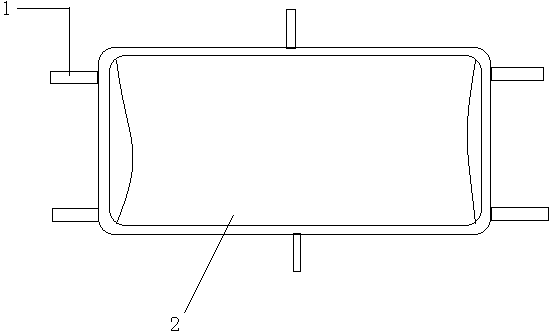
[0013] In order to overcome the problem that the existing stretcher needs to move the patient during the operation and the stretcher can only be carried by two people, the present invention provides such figure 1 , figure 2 A cot shown. It includes a rectangular bed body 2 and handrails 1, each of the four corners of the lower surface of the bed body 2 is provided with a handrail 1, and the inner end of the handrail 1 is movably connected with the lower surface of the bed body 2.

[0014] The armrest 1 can be rotated to the lower surface of the bed body to reduce the size during operation. The two sides of the middle part of the lower surface of the bed body 2 are respectively provided with a movably connected handrail 1 .

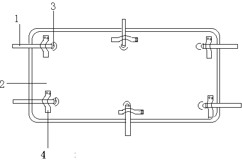
[0015] The armrest 1 is hinged to the lower surface of the bed body 2 through joint bearings or pin shafts.

[0016] The lower surface of the bed body 2 is provided with buckles 4, and the buckles 4 are arranged outside the connecting bearing 3, and th...


PUM


Abstract

The invention provides a multifunctional stretcher, which comprises a rectangular stretcher body and handrails, wherein a handrail is arranged at each corner of the lower surface of the stretcher body; the inner ends of the handrails are movably connected with the lower surface of the stretcher body. According to the multifunctional stretcher, the problem that a patient is required to be moved during scanning is solved; the patient and the stretcher can be simultaneously placed on an operating bed, so that unnecessary pain on the patient during movement is avoided; six handrails are arranged, so that the number of carrying persons is increased, and the patient can be simultaneously carried by four persons.

Description


Claims


Application Information

Patent Timeline
Owner SHAANXI YIFU BEAUTY THERAPY TECH
Why Eureka
Try Eureka