Chemical Vapor Deposition Furnace

A chemical vapor deposition, furnace cover technology, applied in gaseous chemical plating, metal material coating process, coating and other directions, can solve the problem of high temperature

Active Publication Date: 2016-12-07
威科赛乐微电子股份有限公司
View PDF6 Cites 2 Cited by
  • Summary
  • Abstract
  • Description
  • Claims
  • Application Information

AI Technical Summary

Problems solved by technology

The chemical vapor deposition process determines that the chemical vapor deposition furnace has two different thermal fields, and the temperature is relatively high, which poses a challenge to ensure a stable thermal field in the furnace and at the same time ensure its high-temperature working safety

Method used


Image

  • Chemical Vapor Deposition Furnace
  • Chemical Vapor Deposition Furnace
  • Chemical Vapor Deposition Furnace

Examples


Embodiment Construction

[0046] The chemical vapor deposition furnace according to the present invention will be described in detail below with reference to the accompanying drawings.

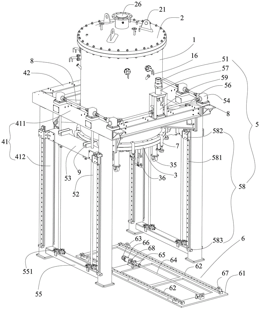
[0047] refer to figure 1 , the chemical vapor deposition furnace according to the present invention comprises: a furnace body 1; an upper furnace cover 2, arranged on the upper part of the furnace body 1, sealed with the furnace body 1 and detachably fixedly connected; a lower furnace cover 3, arranged on the furnace body 1 The lower part is sealed and detachably fixedly connected with the furnace body 1; and the lower furnace cover lifting mechanism 5 is fixedly connected with the lower furnace cover 3, so that the lower furnace cover 3 drives the lower furnace cover 3 after disengaging the fixed furnace body 1 Falling to carry out the lower discharge, and driving the discharged lower furnace cover 3 to rise to combine with the furnace body 1 . The furnace body 1 adopts the bottom discharge method, which is safe, rel...


PUM


Abstract

The invention provides a chemical vapor deposition furnace. The furnace comprises a furnace body; an upper furnace cover which is arranged at the upper portion of the furnace body and is detachably fixedly connected with the furnace body in a sealing manner; a lower furnace cover arranged at the lower portion of the furnace body and in sealed detachable fixed connection with the furnace body; and a lower furnace cover elevating mechanism fixedly connected with the lower furnace cover to make the lower furnace body removed from the fixed furnace body drive the lower furnace cover to fall in order to discharge and drive the lower furnace cover after discharge to rise to be combined with the furnace body. The chemical vapor deposition furnace also comprises a forward / backward pushing mechanism arranged just below the lower furnace cover, and the forward / backward pushing mechanism makes the lower furnace cover elevating mechanism drive the falling lower furnace cover to fall on the forward / backward pushing mechanism and forward / backward move to the periphery in order to carry out discharging and charging. The furnace body, the upper furnace cover and the lower furnace cover adopts a water cooling interlayer and a heat insulating layer respectively. The mutual dislocation of the furnace body in the repeated dismounting process is avoided; the discharging and the charging are safe and reliable, and are convenient to operate; and the stability of the thermal field in the furnace is stable, and the high temperature work safety is improved.

Description

technical field [0001] The invention relates to a heat treatment device, in particular to a chemical vapor deposition furnace. Background technique [0002] The equipment currently applied to chemical vapor deposition mainly adopts the middle part or the upper part of the furnace. For example, the Chinese patent CN202063992U authorized and announced on December 7, 2011 discloses a chemical vapor deposition furnace, wherein the upper side of the upper furnace body in the furnace body is connected to the furnace body lifting mechanism and the upper end of the furnace cover is connected to the upper furnace body. The furnace cover lifting mechanism on the side of the body is connected. Since the furnace body adopts the structure of the furnace cover, upper furnace body, lower furnace body and furnace bottom, this chemical vapor deposition furnace adopts the middle opening method, and the furnace body of this kind of middle opening method The structure is inconvenient for loadi...

Claims


Application Information

Patent Timeline
Patent Type & Authority Patents(China)
IPC IPC(8): C23C16/00C23C16/44
CPCC23C16/00C23C16/44
Inventor 朱刘朱巨才于金凤吴伟平陈松李钦
Owner 威科赛乐微电子股份有限公司
Why Eureka
Try Eureka