Geodetic surveying device with microlens array

A technology of microlens array and geodesy, which is applied in the direction of measuring devices, lenses, measuring instruments, etc., can solve the problems of optical image aberration, aiming accuracy, etc., and achieve the effect of avoiding error sources

Inactive Publication Date: 2015-02-11
HEXAGON TECH CENT GMBH
View PDF15 Cites 7 Cited by
  • Summary
  • Abstract
  • Description
  • Claims
  • Application Information

AI Technical Summary

Problems solved by technology

However, there are aberrations in the optical image due to deviations from mec

Method used


Image

  • Geodetic surveying device with microlens array
  • Geodetic surveying device with microlens array
  • Geodetic surveying device with microlens array

Examples


Embodiment Construction

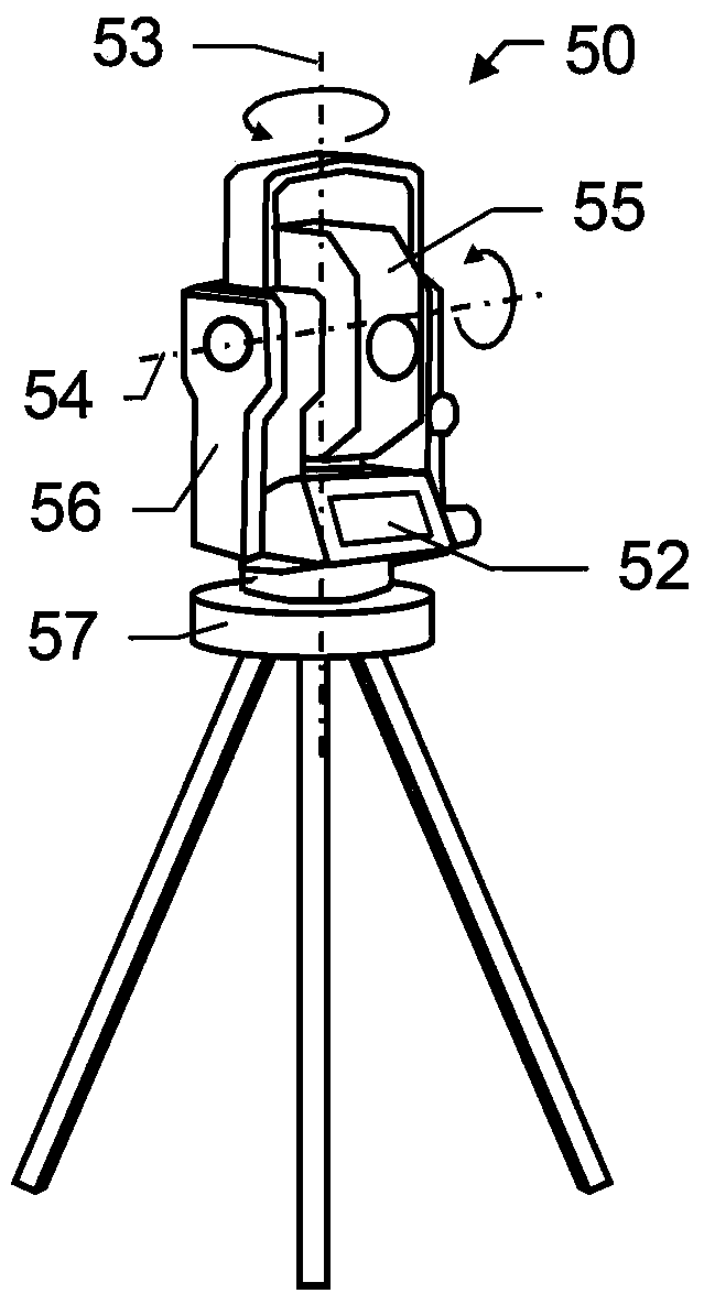
[0075] Figure 1a A geodetic surveying device 50 (in this case, a total station 50 ) according to the prior art is shown, comprising a targeting unit 55 with an image acquisition unit (in particular a camera), wherein the acquisition direction of the image acquisition unit is very It is largely parallel to the measuring direction of the measuring device which is also arranged in the measuring device. Thus, the optical acquisition axis of the integrated image acquisition unit extends at least parallel (in particular, coaxially) to the measurement axis defined by the emitting measurement radiation. The field of view of the image acquisition unit is defined by the optical unit installed in the sighting unit 55 and the design of the sighting unit 55, thereby defining the measurement radiation and the direction of the measurement radiation also manifested by the optical unit.

[0076] Furthermore, the measuring device 50 is provided with an output unit 52 which in particular compr...


PUM


Abstract

Some embodiments relate to a geodetic surveying device, comprising a beam source for generating measurement radiation, a base defining a vertical axis, a support carrying a targeting unit and defining a tilt axis, the support being arranged on the base and rotatable relative to the base about the vertical axis, and the targeting unit being arranged rotatable relative to the support about the tilt axis, and an angle- and distance-measuring functionality. Moreover, provision is made for an image acquisition unit for acquiring images of an object in a field of view defined by the image acquisition unit, and a control and processing unit. The image acquisition unit comprises at least an image sensor and a microlens array with a multiplicity of diffractive and/or refractive optical elements arranged in a defined two-dimensional manner.

Description

technical field [0001] The invention relates to a geodetic surveying device for measuring target points according to the preamble of claim 1 and to the method according to the invention for such a surveying device according to claim 11 and to the method according to claim 15 . The computer program product described. Background technique [0002] For measuring target points, numerous geodetic devices have been known since ancient times. In this case, the direction or angle and often also the distance from the measuring device to the target point to be measured are recorded, in particular, the absolute position of the measuring device is detected together with possibly existing reference points as spatial norm data. [0003] Well-known examples of such geodetic devices include theodolites, tachymeters, and total stations, also designated electronic tachymeters or computer tachymeters. For example, a prior art geodetic device is described in publication EP 1686350. Such a de...

Claims


Application Information

Patent Timeline
IPC IPC(8): G01C15/00G02B3/00
CPCG01C3/08G01C11/02G01C15/00G01C1/04
Inventor J·辛德林伯恩哈德·麦茨勒
Owner HEXAGON TECH CENT GMBH
Why Eureka
Try Eureka