Colorimetry apparatus

A color measuring device, a technology of parallel light, applied in the direction of measuring device, color measuring device, color measurement using electric radiation detector, etc.

Inactive Publication Date: 2015-02-11
SEIKO EPSON CORP
View PDF4 Cites 3 Cited by
  • Summary
  • Abstract
  • Description
  • Claims
  • Application Information

AI Technical Summary

Problems solved by technology

That is, the illuminance becomes lower at a position with a longer optical path length than at a position with a shorter optical path length from the collimator lens to the surface to be measured.
When the color measurement device measures the color at multiple points instead of one point on the surface to be measured, the uneven illumination becomes the main cause of the decrease in measurement accuracy.

Method used


Image

  • Colorimetry apparatus
  • Colorimetry apparatus
  • Colorimetry apparatus

Examples


no. 1 approach

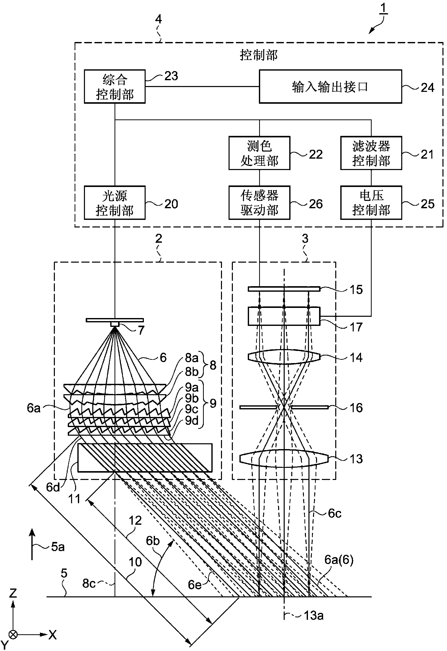
[0045] according to figure 1 ˜ FIG. 5 illustrate the colorimetric device according to the first embodiment. figure 1 It is a schematic configuration diagram showing the configuration of the colorimetric device. Such as figure 1 As shown, the colorimetric device 1 includes a light projecting unit 2 , an imaging unit 3 , and a control unit 4 . The light projecting part 2 is a part that irradiates the light 6 to the surface to be measured 5 . The imaging unit 3 is a part that receives the light 6 c reflected by the measurement surface 5 . The control unit 4 controls the light projecting unit 2 and the imaging unit 3 . The imaging unit 3 is provided at a position opposite to the position where the light projecting unit 2 irradiates the light 6 . The direction traveling from the light projecting unit 2 to the imaging unit 3 is set as the X direction. Furthermore, a surface to be measured 5 is provided at a position facing the light projecting unit 2 and the imaging unit 3 . ...

no. 2 approach

[0090] Next, an embodiment of a filter provided in a colorimetric device will be described using FIG. 6 . Fig. 6(a) is a schematic perspective view showing the structure of a filter. FIG. 6( b ) is a schematic perspective view showing the structure of the upper filter, and FIG. 6( c ) is a schematic perspective view showing the structure of the lower filter. This embodiment differs from the first embodiment in that the structure of the filter 11 is different. In addition, the description of the same points as those of the first embodiment will be omitted.

[0091] That is, in this embodiment, as shown in FIG. 6 , a filter 46 is used in the colorimetric device 45 . The filter 46 has the same function as the filter 11 in the first embodiment. In the filter 46 , a plate-shaped upper filter 48 is stacked on a plate-shaped lower filter 47 . As shown in FIG. 6( b ), the light transmitting portions 48 a and the light absorbing portions 48 b of the upper filter 48 are alternately ...

no. 3 approach

[0097] Next, an embodiment of the colorimetric device will be described using FIG. 7 . 7( a ) is a schematic plan view showing the structure of the colorimetric device, and FIG. 7( b ) is a schematic side view showing the structure of the colorimetric device. In addition, the description of the same points as those of the first embodiment will be omitted.

[0098] That is, in this embodiment, as shown in FIG. . Each of the first light projecting unit 52 to the fourth light projecting unit 55 has the same function as that of the light projecting unit 2 in the first embodiment. The first light projecting unit 52 is located on the Y-direction side of the imaging unit 3 , and emits parallel light 6 a onto the surface to be measured 5 at a position facing the imaging unit 3 . The second light projecting unit 53 is located on the X-direction side of the imaging unit 3 , and irradiates parallel light 6 a to the surface to be measured 5 at a position facing the imaging unit 3 . Th...


PUM


Abstract

A colorimetry apparatus includes a light projection unit that irradiates a surface under measurement with light and an imaging unit that captures an image of the surface under measurement. The light projection unit includes a light source, a collimator lens that converts light emitted from the light source into parallelized light, and a traveling direction changer that changes the traveling direction of the parallelized light while maintaining parallelism of the parallelized light. The traveling direction changer is disposed in parallel to the surface under measurement, and the direction of the optical axis of the collimator lens coincides with the direction of a normal to the surface under measurement.

Description

[0001] The entire disclosure of Japanese Patent Application No. 2013-163040 with a filing date of June 8, 2013 is expressly incorporated herein by reference. technical field [0002] The invention relates to a color measuring device. Background technique [0003] A color measuring device that measures and evaluates the color of an object objectively and with high accuracy is widely used. In addition, the method of irradiating light when measuring color is prescribed in JISZ8722. According to this method, one of the methods of irradiating light is to irradiate the sample with a beam of light at 45±2° with respect to the normal to the surface of the sample. Then, the reflected light with an angle of 10° or less to the normal line of the sample surface is received and measured. Irradiating and receiving beams of light are limited within an inclination of 8° relative to the centerline. In addition, this measuring method is a measuring method of object color according to the p...

Claims


Application Information

Patent Timeline
Patent Type & Authority Applications(China)
IPC IPC(8): G01J3/46
CPCG01J3/50G01J3/0208G01J3/0205G01J3/0264G01J3/26G01J3/51
Inventor 舟本达昭
Owner SEIKO EPSON CORP
Why Eureka
Try Eureka