Supercharge Your Innovation With Domain-Expert AI Agents!

amplifying circuit

A technology of amplifying circuit and matching circuit, which is applied in amplifiers, high-frequency amplifiers, differential amplifiers, etc., and can solve problems such as poor nonlinear performance of amplifying circuits

Active Publication Date: 2017-12-15
NXP BV
View PDF5 Cites 0 Cited by
  • Summary
  • Abstract
  • Description
  • Claims
  • Application Information

AI Technical Summary

Problems solved by technology

[0002] Amplifying circuits usually have poor nonlinear performance (for example, in terms of IM2 and IM3 suppression), and existing amplifying circuits require more surface mount devices or components

Method used


Image

  • amplifying circuit
  • amplifying circuit
  • amplifying circuit

Examples


Embodiment Construction

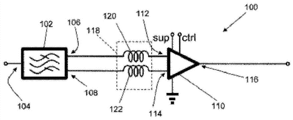
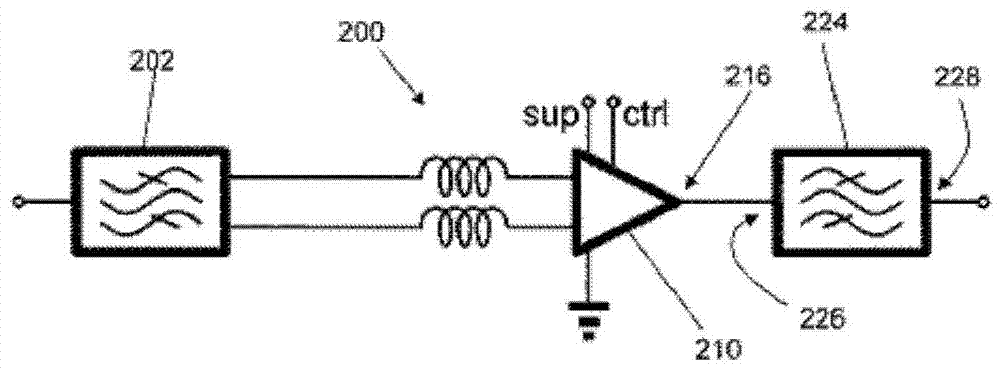
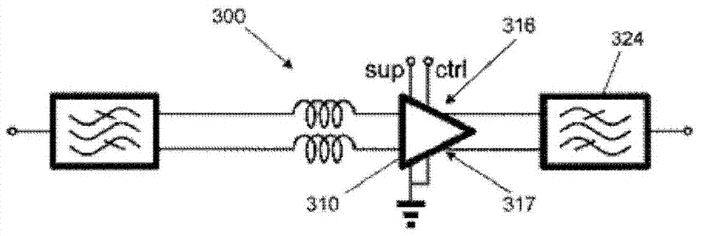
[0051] One or more embodiments disclosed herein relate to an amplifying circuit comprising: a first filter and a low noise amplifier (LNA). In particular, the first filter may be an acoustic wave filter, such as a surface acoustic wave (SAW) filter or a bulk acoustic wave (BAW) filter, having a balanced / differential signal output connected to a balanced / differential signal input of the low noise amplifier. The combination of components can provide good non-linear performance (eg in terms of IM2 and IM3 rejection), yet requires fewer surface mount components / components than other amplifier circuits. Improved performance, especially in IM3, can be provided by an acoustic filter that performs differential-mode operation for frequencies within the passband and common-mode operation for frequencies outside the passband. Such amplifier circuits can be used particularly preferably in GPS receivers.

[0052] figure 1 An amplifying circuit 100 is shown, including: a first filter 102 ...


PUM


Abstract

An amplification circuit (100) comprising a first filter (102) and an LNA (110). The first filter (102) comprising an input (104) for receiving an input signal; a first differential output (106); and a second differential output (108). The first filter (102) has a differential mode of operation for frequencies in its pass-band (706, 806) and a common mode of operation for frequencies outside its pass-band (706, 806), and may be an acoustic wave filter. The LNA (110) comprising a first differential input (112) connected to the first differential output (106) of the first filter (102); a second differential input (114) connected to the second differential output (108) of the first filter (102); and an output (116) for providing an amplified output signal.

Description

technical field [0001] This application relates to amplification circuits and in particular, though not necessarily, to amplification circuits for use in global positioning system receivers. Background technique [0002] Amplifying circuits generally have the problem of poor nonlinear performance (for example, in IM2 and IM3 suppression), and existing amplifying circuits require many surface-mounted devices or components. Contents of the invention [0003] According to a first aspect of the present invention, an amplifying circuit is provided, comprising: [0004] First filter, including: [0005] an input terminal for receiving an input signal; [0006] a first differential output; and [0007] a second differential output; [0008] wherein the first filter performs differential-mode operation for frequencies within its passband and common-mode operation for frequencies outside its passband; and [0009] Low Noise Amplifiers (LNAs), including: [0010] a first diffe...

Claims


Application Information

Patent Timeline
Patent Type & Authority Patents(China)
IPC IPC(8): H03F3/45
CPCH03F3/45071H03F1/02H03F1/3211H03F1/56H03F3/19H03F2200/165H03F2200/171H03F2200/294H03F2203/45148H03F2203/45544H03F2203/45554H03H7/075H03H7/38H03H9/02535H04B1/7097
Inventor 马尔切利尼斯·约翰内斯·玛里亚·吉尔兹路易斯·普拉姆斯玛米歇尔·威尔默斯·阿纳尔德斯·格鲁尼维根雷尼尔·布鲁尼塞弗雷克·范斯坦滕罗伯特·维克托·布坦胡斯
Owner NXP BV
Features
  • R&D
  • Intellectual Property
  • Life Sciences
  • Materials
  • Tech Scout
  • Unparalleled Data Quality
  • Higher Quality Content
  • 60% Fewer Hallucinations
Learn More