
Signal joint detection method and device

A joint detection and signal technology, applied in transmission systems, electrical components, etc., can solve problems such as large distortion of transmitted data symbol sequences, and achieve the effect of reducing computational complexity

Inactive Publication Date: 2018-07-31
MARVELL ASIA PTE LTD
View PDF8 Cites 0 Cited by
  • Summary
  • Abstract
  • Description
  • Claims
  • Application Information

AI Technical Summary

Problems solved by technology

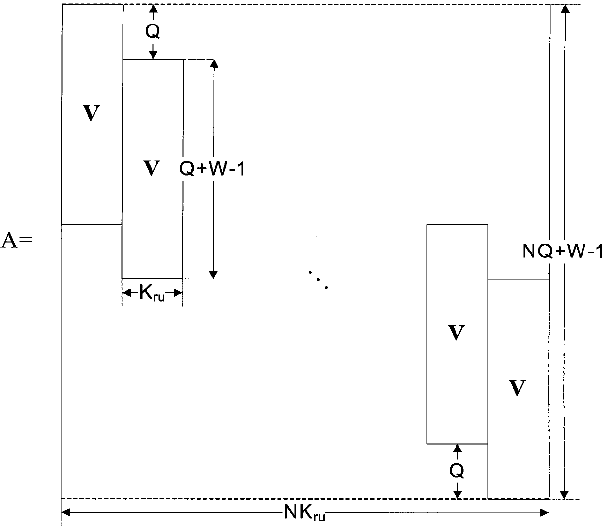
For the "CIR split method", since the channel impulse response is split, a non-real system matrix A is obtained based on the non-real channel impulse response, and then a non-real system matrix A is obtained based on the non-real system matrix A matrix A H A, so that the estimate of the transmitted data symbol sequence obtained by the above formula (3) with large distortion

Method used


Image

  • Signal joint detection method and device
  • Signal joint detection method and device
  • Signal joint detection method and device

Examples


Embodiment Construction

[0042] Preferred embodiments of the present disclosure will be described in more detail below with reference to the accompanying drawings. Although preferred embodiments of the present disclosure are shown in the drawings, it should be understood that the present disclosure may be embodied in various forms and should not be limited to the embodiments set forth herein. Rather, these embodiments are provided so that this disclosure will be thorough and complete, and will fully convey the scope of the disclosure to those skilled in the art.

[0043] In the context of this disclosure, a user equipment (UE) may refer to a terminal, mobile terminal (MT), subscriber station (SS), portable subscriber station (PSS), mobile station (MS) or access terminal (AT), and Some or all of the functionality of a UE, terminal, MT, SS, PSS, MS, or AT may be included.

[0044] Furthermore, in the context of the present disclosure, a base station (BS) may eg mean a Node B (NodeB or NB), an Evolved N...


PUM


Abstract

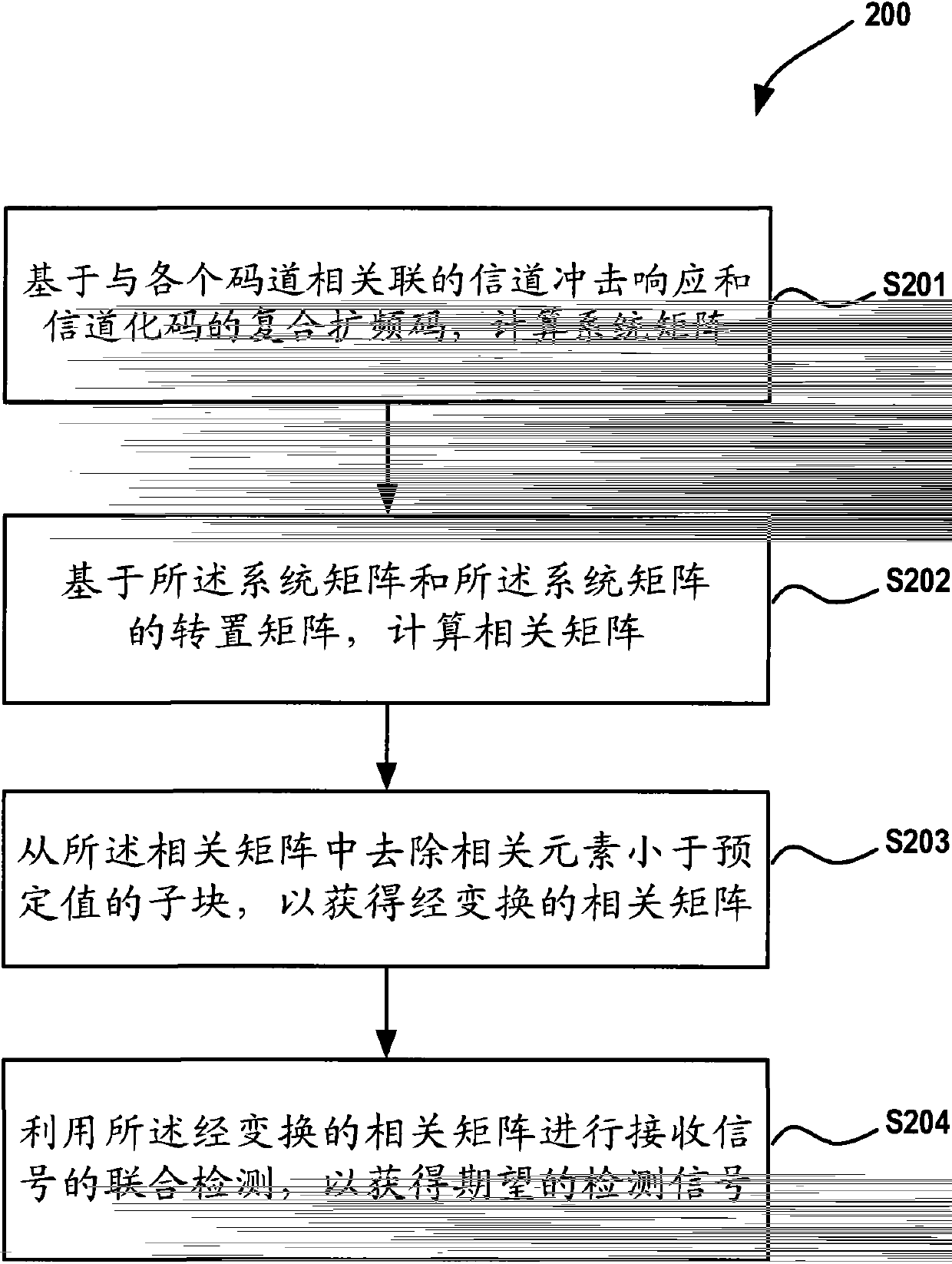
The embodiment of the invention provides a signal joint inspection method and device. The method comprises calculating a system matrix based on channel impulse responses related to each code channel and complex spreading codes of channelized codes; calculating a correlation matrix based on the system matrix and a transpose of the system matrix; removing a sub-block the coherent element of which is smaller than a preset value from the correlation matrix to obtain a converted correlation matrix; carrying out joint inspection of received signals by means of the converted correlation matrix to obtain expected detection signals. According to the invention, detection signals with less distortions can be obtained. Furthermore, when the joint inspection is carried out, only one matrix inversion calculation is needed, and therefore the calculation complexity is reduced.

Description

[0001] Cross References to Related Applications [0002] This application claims priority to U.S. Provisional Application No. 61 / 858,894, filed July 26, 2013, and U.S. Provisional Application No. 61 / 858,920, filed July 26, 2013, the disclosures of which are incorporated by reference All incorporated herein. technical field [0003] Various embodiments of the present invention relate to the technical field of wireless communication, and more specifically relate to a method and device for joint detection of signals. Background technique [0004] Time Division Synchronous Code Division Multiple Access (TD-SCDMA) system is a synchronous system, and the time of each base station is synchronized. A user equipment (UE) may receive signals from multiple cells including a serving cell and a neighboring cell, and a base station may also receive signals from a UE in a serving cell and a UE in a neighboring cell, wherein the signal of a neighboring cell belongs to interference. Sinc...

Claims


Application Information

Patent Timeline
Patent Type & Authority Patents(China)
IPC IPC(8): H04B1/7105H04B1/7107
Inventor 陈冠郑明朱学庆刘石
Owner MARVELL ASIA PTE LTD
Learn More