Lifting hydraulic control system

A technology of hydraulic control system and hydraulic control valve, which is applied in the direction of lifting frame, lifting device, fluid pressure actuating device, etc., which can solve problems such as prone to failure, limited height, and inability to lift large objects, so as to ensure stability , Strong lifting capacity and stable lifting effect

Active Publication Date: 2015-02-18
TAIXING TALI MACHINERY MFG
View PDF7 Cites 0 Cited by
  • Summary
  • Abstract
  • Description
  • Claims
  • Application Information

AI Technical Summary

Problems solved by technology

Traditional lifting devices usually have the following limitations: 1. The lifting height is limited, and the transportation between floors of buildings cannot be realized; 2. The size of the lifting platform is limited, and large objects cannot be lifted, and the balance of the

Method used


Image

  • Lifting hydraulic control system
  • Lifting hydraulic control system

Examples


Example Embodiment

[0018] The specific embodiments of the present invention will be described in further detail below with reference to the accompanying drawings:

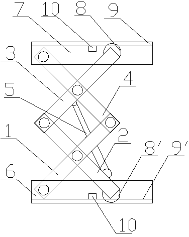
[0019] As shown in the figure: a lifting device, including a lifting mechanism and a hydraulic control system, the lifting mechanism includes two sets of lifting units, the lifting unit includes a lower support plate 6, an upper lifting platform 7 and Four support arms, the support arm consists of two parallel support rods, the ends and the middle of the two support rods are fixedly connected with cross bars;

[0020] A lower rail 9'is provided on the top surface of the lower support plate 6, and an upper rail 9 is provided on the bottom surface of the upper lifting platform 7,

[0021] A position switch 10 is provided on the upper rail 9 and the lower rail 9', and the position of the position switch 10 on the rail is adjustable; the first support arm 1 and the second support arm 2 are arranged in an X-shaped cross, The intermediate posi...


PUM


Abstract

The invention relates to a lifting hydraulic control system which comprises an oil tank, a hydraulic pump and a hydraulic control circuit, wherein an input end of the hydraulic pump is connected with the oil tank via a pipeline; the lifting hydraulic control system is characterized in that an output end of the hydraulic pump is connected with the P port of a three-position four-way valve; the T port of the three-position four-way valve is connected with the oil tank via a pipeline; the A port of the three-position four-way valve is connected with an input end of a balance valve; each of the two input ends of the balance valve is connected with an input end of each of two hydraulic control valves; the B port of the three-position four-way valve is divided into two branches, and each of the two branches is connected with the other input end of each of the hydraulic control valves; the output ends of the hydraulic control valves are connected with the input ends of corresponding hydraulic cylinders; electromagnetic valve reversing valve branches are arranged on pipelines between the hydraulic control valves and the input ends of the hydraulic cylinders; input ends of electromagnetic reversing valves are connected with the input ends of the hydraulic cylinders; two output ends of the electromagnetic reversing valves are connected with the oil tank via pipelines respectively; the hydraulic pump, a three-way electromagnetic valve and the electromagnetic reversing valves are connected with the control circuit.

Description

technical field [0001] The invention relates to a lifting device, in particular to a hydraulic control of the lifting device. Background technique [0002] The lifting device is generally used for the vertical transportation of heavy objects, such as the up and down transportation of goods between building floors, the lifting of cars between the floors of three-dimensional garages and underground garages, and the lifting of working platforms. Traditional lifting devices usually have the following limitations: 1. The lifting height is limited, and the transportation between floors of buildings cannot be realized; 2. The size of the lifting platform is limited, and large objects cannot be lifted, and the balance of the lifting platform No, the position of the lifted object needs to be adjusted repeatedly before lifting to prevent tipping during the lifting process; 3. The hydraulic power system does not have anti-drop and overload protection functions, and is prone to fail...

Claims


Application Information

Patent Timeline
IPC IPC(8): B66F7/08F15B11/00
CPCB66F7/0666B66F7/08B66F7/28F15B11/22F15B13/06
Inventor 叶家俊
Owner TAIXING TALI MACHINERY MFG
Why Eureka
Try Eureka