Cap rotating mechanism

A technology of capping and capping, which is applied to screw caps and other directions, which can solve problems such as the inability of the machine to run stably

Active Publication Date: 2015-02-18
GUANGZHOU TECH LONG PACKAGING MACHINERY CO LTD
View PDF9 Cites 2 Cited by
  • Summary
  • Abstract
  • Description
  • Claims
  • Application Information

AI Technical Summary

Problems solved by technology

When the capping machine is running at high speed, t

Method used


Image

  • Cap rotating mechanism
  • Cap rotating mechanism
  • Cap rotating mechanism

Examples


Embodiment Construction

[0029] Embodiments of the present invention are described in detail below:

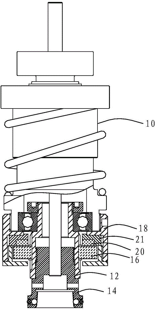
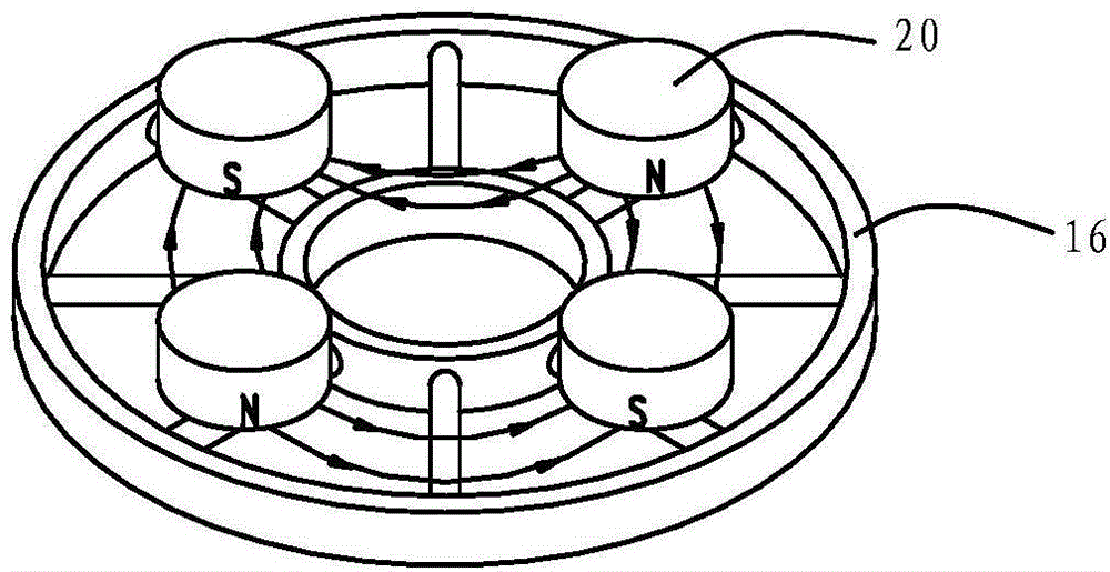
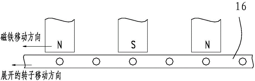
[0030] like Figure 1 to Figure 3 Shown, a kind of screw cap mechanism, it comprises screw cap main body 10, rotating shaft 12, catch cap head 14, disc rotor 16 and magnet fixing base 18; The bottom of described screw cap main body 10 and the top of described rotating shaft 12 Fixedly connected, the bottom of the rotating shaft 12 is fixedly connected with the cap gripping head 14, and the rotating shaft 12 is driven by the rotation of the cap main body 10 to rotate the capping head 14. The disc rotor 16 and the rotating shaft 12 The outer circumference of the magnet fixing base 18 is fixed with an upper magnet 20 or a lower magnet, the upper magnet 20 is located above the disc rotor 16, or the lower magnet is located below the disc rotor 16, and the upper Both the magnet 20 and the lower magnet include N magnetic regions and S magnetic regions, and the N magnetic regions and the S magnetic regions a...


PUM


Abstract

The invention discloses a cap rotating mechanism, which comprises a cap rotating main body, a rotating shaft and a cap grasping head, wherein the rotating shaft rotates in the cap rotating main body and is also fixedly connected with the cap grasping head, the cap rotating mechanism also comprises a magnet fixing seat and a disc-shaped rotor, the magnet fixing seat and the cap rotating main body are fixed, an upper magnet or a lower magnet is fixedly arranged on the magnet fixing seat, the upper magnet is positioned above the disc-shaped rotor, or the lower magnet is positioned under the disc-shaped rotor, each of the upper magnet and the lower magnet comprises an N magnetic region and an S magnetic region, the N magnetic regions and the S magnetic regions are in staggered arrangement, and the disc-shaped rotor is fixed with the rotating shaft. The magnet is arranged above or under the magnet fixing seat, and in addition, the N magnetic region and the S magnetic region in adjacent arrangement generate effective magnetic fields on the disc-shaped rotor, so that the cap grasping head generates a certain amount of overload torque, the transition of the cap grasping head overload torque is smooth, the operation is stable, and the high-speed operation of the cap grasping head can be realized.

Description

technical field [0001] The invention relates to the technical field of packaging, in particular to a screw cap mechanism. Background technique [0002] The capping mechanism in the prior art is provided with two circles of active magnets and driven magnets which are evenly distributed in an annular shape. The active magnets are installed on the capping body. When the capping machine drives the capping mechanism to rotate, the capping body drives the active magnet to rotate. , The driven magnet installed on the rotating shaft rotates under the drive of the magnetic force. When the cap screwing mechanism is screwing the cap, the cap grasping mechanism installed on the rotating shaft will screw the cap onto the bottle under the drive of magnetic force. When the cap is screwed tightly, the cap is fixed on the bottle, so that the driven magnet, the rotating shaft, the cap gripping mechanism and the cap stop rotating, and the active magnet keeps rotating with the main body of the...

Claims


Application Information

Patent Timeline
IPC IPC(8): B67B3/20
CPCB67B3/20
Inventor 张聪敏杨恢光
Owner GUANGZHOU TECH LONG PACKAGING MACHINERY CO LTD
Why Eureka
Try Eureka