Press with spindle drive

a spindle drive and press technology, applied in the field of press, can solve the problems of destroying drive train parts, affecting the operation of the press, and affecting the operation of the press, and achieve the effect of eliminating the tolerance of individual spring elements

Pending Publication Date: 2020-05-14
GEBR SCHMIDT FAB FUER FEINMECHANIK GMBH & CO KG
View PDF1 Cites 1 Cited by
  • Summary
  • Abstract
  • Description
  • Claims
  • Application Information

AI Technical Summary

Benefits of technology

[0037]It is preferable if not just one spring element but a multiplicity of spring elements is used for the resilient support of the second latching disk in the housing. The use of a plurality of sprin...

Problems solved by technology

In such presses, but also in other machines in which spindle drives are used as part of highly dynamic systems with end-contact or collision travel, extremely high peak forces occur due to the mass moments of inertia of the motor and of the spindle system.
These peak forces which occur in the case of end-contact or collision travel can destroy parts of the drive train.
One significant disadvantage of linear overload clutches is the extremely large overall lengths and the fact that the disengagement stroke is limited.
Another problem is that of bringing a disengaged linear clutch back into its initial state.
For these reasons, linear overload clutches of this kind are not very suitable for the use intended in the present case in electric pr...

Method used


Image

  • Press with spindle drive
  • Press with spindle drive
  • Press with spindle drive

Examples


first embodiment

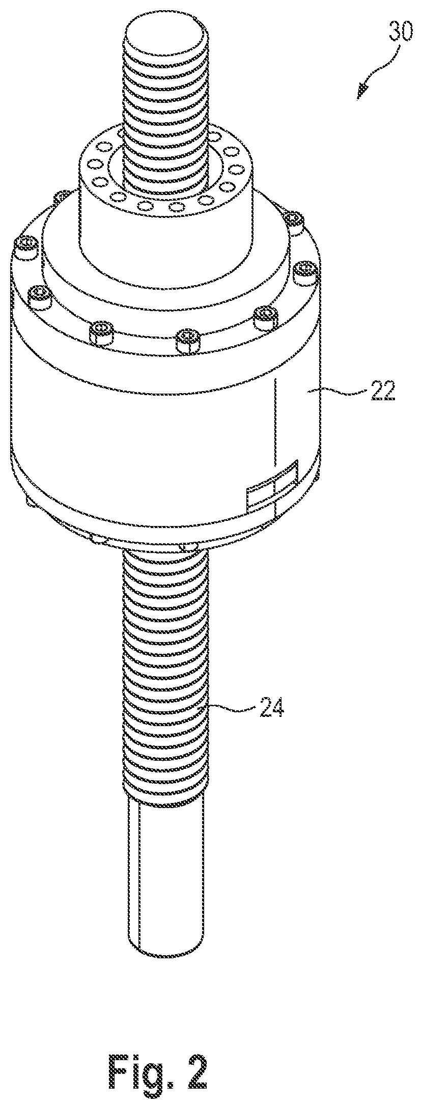
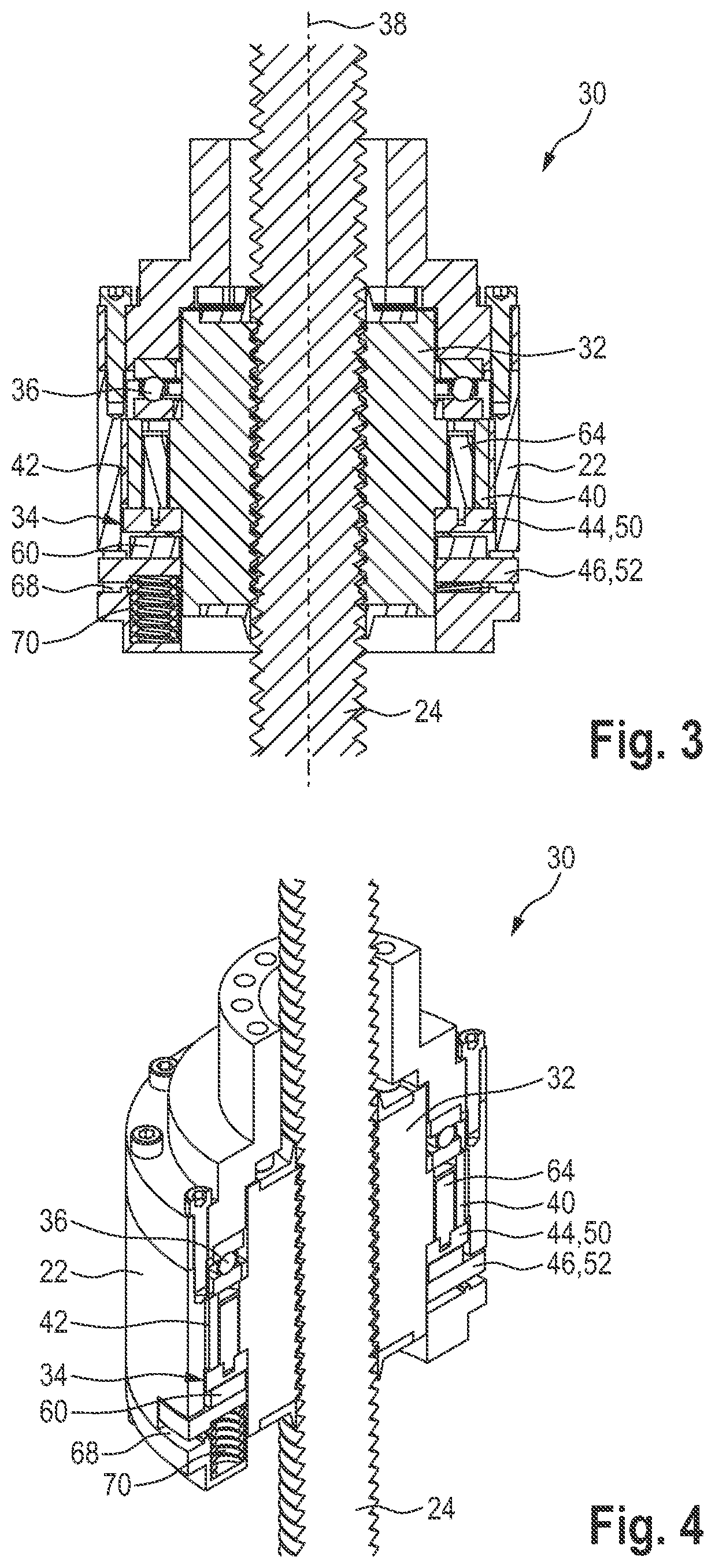
[0062]FIG. 2 shows the spindle drive 30 in a perspective illustration. Further sections and half-sections are shown in FIGS. 3 and 4.

[0063]In addition to the housing 22 and the spindle 24, the spindle drive furthermore comprises a spindle nut 32 mounted on the spindle 24. The illustrative embodiment of the spindle drive 30 in the present case is a spindle drive with a driven spindle nut 32. Accordingly, the spindle nut 32 is driven in rotation, thereby bringing about a purely translational motion of the spindle 24 (without rotation). To be able to ensure this, the spindle 24 is provided with an anti-rotation safeguard (not shown). The spindle nut 32 is driven indirectly in that the housing 22 is driven by the drive motor 20. The housing 22 is therefore connected in a fixed manner to the drive shaft of the drive motor 20. The drive motor 20 is preferably designed as a hollow shaft motor, and therefore the housing 22 is inserted partially or entirely into the hollow shaft 21 of the dr...

second embodiment

[0082]A difference of the second embodiment consists in the type of embodiment of the overload clutch 34′. Here, the second clutch component 46′ is not configured as a latching disk but comprises a plurality of holders 82, in each of which a latching element 48′ is resiliently mounted. The latching elements 48′ are of substantially bar-shaped configuration. The holders 82 are arranged in the housing 22′ in such a way that the latching elements 48′ are movable in the radial direction, i.e. perpendicularly to the longitudinal axis 38′ of the spindle 24′.

[0083]In the second embodiment, the first clutch component 44′ is configured as a sleeve 80, which surrounds the spindle nut 32′ or is placed on the latter. The sleeve 80 comprises a plurality of grooves 84, in which the rod-shaped latching elements 48′ engage in the latched position (see FIG. 9).

[0084]In a similar or identical way to the first embodiment, the sleeve 80 which forms the first clutch component 44′ is connected to the spi...


PUM


Abstract

A spindle drive having a spindle, a spindle nut which is arranged on the spindle, a housing which surrounds the spindle nut, and an overload clutch which is arranged in the housing. The spindle nut and the housing are connected to one another via the overload clutch. The overload clutch is set up to disconnect the spindle nut from the housing in a torque-free manner if a defined overload torque which acts between the spindle nut and the housing is exceeded.

Description

CROSS REFERENCE TO RELATED APPLICATIONS[0001]This application is a continuation of international patent application PCT / EP2018 / 069666, filed on Jul. 19, 2018 designating the U.S., which international patent application has been published in German language and claims priority from German patent application DE 10 2017 116 271.2, filed on Jul. 19, 2017. The entire contents of these priority applications are incorporated herein by reference.BACKGROUND OF THE INVENTION[0002]This disclosure relates to a press, in particular an electric press, in which a spindle drive is used. Presses of this kind are used predominantly as joining presses. Spindle drives are used essentially to convert a rotary motion produced by a motor (generally an electric motor) into a linear motion, generating large forces. They have a spindle, which is often also referred to as a leadscrew, and a spindle nut mounted on the spindle. Depending on the configuration of the spindle drive, the spindle and the spindle nut...

Claims


Application Information

Patent Timeline
IPC IPC(8): B30B1/18B30B15/12B30B15/28F16H25/20
CPCF16H2025/2075B30B1/18B30B15/12B30B15/281F16H25/2021F16H2025/2078
Inventor MEYER, ANDREAS LEONEFF, THOMAS
Owner GEBR SCHMIDT FAB FUER FEINMECHANIK GMBH & CO KG
Why Eureka
Try Eureka