Diffracted wave separating and imaging method based on reflected energy prediction

A technology of reflected energy and imaging method, applied in special data processing applications, instruments, electrical digital data processing, etc., can solve the problem of ignoring scattering effects, etc., to achieve the effect of improving imaging resolution

Inactive Publication Date: 2015-02-18
李晓峰
View PDF2 Cites 15 Cited by
  • Summary
  • Abstract
  • Description
  • Claims
  • Application Information

AI Technical Summary

Problems solved by technology

[0003] However, at this stage, traditional data processing or migration is often aimed at imaging and enhancing the reflected wave energy, and there are often the following unfavorable factors for imaging diffraction targets in some conventional processing procedures: 1) In NMO / DMO, In processes such as velocity analysis, events from outside the reflection layer are usually regarded as interference noise filtering; 2) Most conventional migration algorithms are aimed at imaging specular reflection information, for example, kirchhoff migration usually assumes high frequency or phase stability Approximately, even the traditional diffraction stacking is more inclined to image the reflected wave and ignore the scattering effect; 3) On the seismic section, the amplitude of the diffracted wave is usually weaker than the reflected wave by one to two orders of magnitude, even if it is offset , which is usually also masked by reflection information

Method used


Image

  • Diffracted wave separating and imaging method based on reflected energy prediction
  • Diffracted wave separating and imaging method based on reflected energy prediction
  • Diffracted wave separating and imaging method based on reflected energy prediction

Examples


Embodiment Construction

[0028] In order to make the above and other objects, features and advantages of the present invention more comprehensible, preferred examples are listed below and described in detail in conjunction with the accompanying drawings.

[0029] 1) Select the Sigsbee2a model for testing. The model has 2133 CDP points in the horizontal direction and 1201 sampling points in the vertical direction. The vertical and horizontal sampling intervals are 7.62m and 11.43m respectively. figure 1 shown;

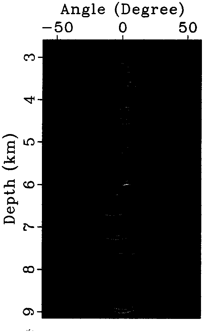
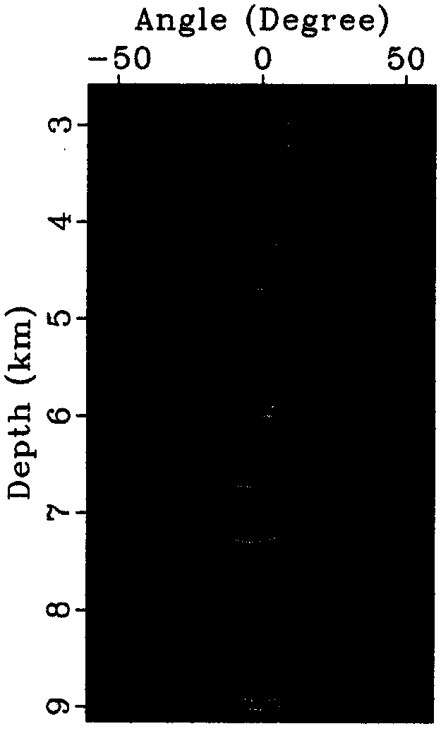
[0030] 2) The observation system used is shooting in the middle and receiving on both sides, a total of 500 shots, the distance between shots is 45.72m, the maximum number of traces per shot is 348, and the distance between traces is 22.86m. exist figure 1 The dip angle gather extracted at the position of the red vertical line (just above the two diffraction points) is shown in figure 2 , the diffraction event is a horizontal straight line (indicated by the solid arrow), and the energy is re...


PUM


Abstract

The invention belongs to a geophysical exploration technology, and relates to a diffracted wave separating and imaging method based on reflected energy prediction. The diffracted wave separating and imaging method comprises the following steps of performing common-angle prestack depth migration on shot records to obtain a dip angle region common-imaging point gather after seismic data are acquired; predicting reflected wave from a full-wave-field common-imaging point gather according to significant difference of tracing patterns of the reflected waves and diffracted waves in the dig angle region common-imaging point gather; performing image similar matching on a predicted dip angle gather containing reflected energy only and a full-wave-field dip angle gather so as to remove reflected energy in a full wave field; using rest energy as diffracted response; and superposing the dip angle region common-imaging point gather which is pressed by a reflected common-phase axis along the dip angle direction to obtain an imaging result comprising diffracted energy mainly. The diffracted wave separating and imaging method based on the reflected energy prediction is a diffracted wave separating and imaging technology which is practical and is convenient to operate.

Description

technical field [0001] The invention relates to seismic data processing, which belongs to the migration imaging processing of seismic data, in particular to a diffraction imaging method based on reflection energy prediction which can improve the imaging resolution of a non-homogeneous diffraction target body. Background technique [0002] The most obvious and most valuable seismic response waveforms in seismic records mainly include reflected waves and diffracted waves. In a narrow sense, the formation conditions of reflected waves and diffracted waves mainly depend on the relationship between the scale of geological bodies and the wavelength of seismic waves: when the scale of geological bodies is much larger than the wavelength of seismic waves, reflected waves are generated; when the scale of geological bodies is equivalent to the wavelength of seismic waves Or when it is smaller than the wavelength of the seismic wave, a diffracted wave is generated. It can be seen that...

Claims


Application Information

Patent Timeline
Patent Type & Authority Applications(China)
IPC IPC(8): G01V1/30G01V1/34G06F19/00
Inventor 李晓峰黄建平李继光赵胜天刘培君李振春段心彪郭书娟
Owner 李晓峰
Why Eureka
Try Eureka