Supercharge Your Innovation With Domain-Expert AI Agents!

A kind of perforating unit ejector live connection

A technology of ejector and union, applied in metal processing equipment, metal rolling, manufacturing tools, etc., can solve the problems of increasing material and machining time consumption, misalignment between the axis of the plug and the axis of the ejector, affecting the accuracy of the wall thickness of the finished product, etc. , to achieve the effect of reducing material consumption, simplifying on-site operations, and avoiding difficult disassembly

Active Publication Date: 2016-06-29
JIANGSU VALIN XIGANG SPECIAL STEEL
View PDF7 Cites 0 Cited by
  • Summary
  • Abstract
  • Description
  • Claims
  • Application Information

AI Technical Summary

Problems solved by technology

[0004] (2) There is relative movement between the plug joint and the ejector pin joint, which will cause wear and tear of related parts after a long time, and burrs are prone to appear, making disassembly difficult;
[0005] (3) Since the locking between the jack and tail handle and the jack joint is realized by two symmetrically arranged cylindrical pins, in order to facilitate disassembly, the diameter of the positioning pin used is smaller than that of the pin hole of the jack joint and the jack joint. The diameter of the semi-circular groove should be smaller, so that the plug is likely to be insufficiently locked during use, resulting in misalignment of the axis of the plug and the axis of the ejector rod, which seriously affects the wall thickness accuracy of the finished product;
[0006] (4) The plug must be equipped with a tail handle during production, which increases the consumption of materials and machining hours. The plug is a vulnerable part, and the cost is huge;
[0007] How to ensure the convenience of disassembly of the plug, ensure the assembly quality of the plug, and reduce the manufacturing cost of the plug for the unit that does not adopt the automatic plug replacement system is a problem that researchers need to study

Method used


Image

  • A kind of perforating unit ejector live connection
  • A kind of perforating unit ejector live connection
  • A kind of perforating unit ejector live connection

Examples


Embodiment Construction

[0025] The present invention will be further explained below in conjunction with the accompanying drawings and specific embodiments. It should be understood that the following specific embodiments are only used to illustrate the present invention and are not intended to limit the scope of the present invention. It should be noted that the words "front", "rear", "left", "right", "upper" and "lower" used in the following description refer to the directions in the drawings, and the words "inner" and "outer ” refer to directions towards or away from the geometric center of a particular part, respectively.

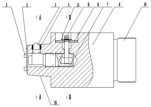
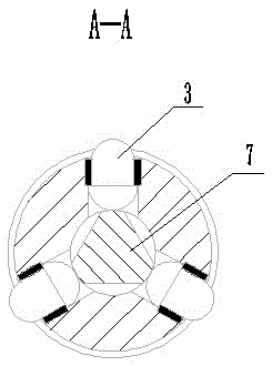
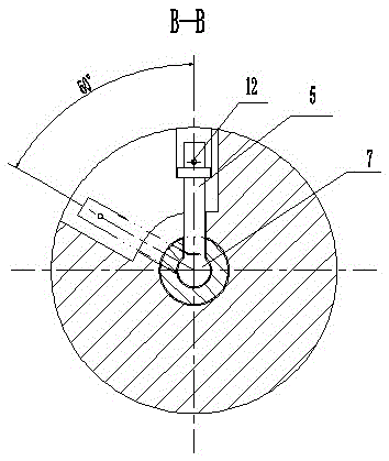
[0026] As shown in the figure, the ejector rod joint of a piercing unit according to the present invention includes a front cone 11, a middle base 8, and a rear screw 10. The middle of the front end of the cone 11 extends backward. There is a blind hole, the shaft 7 of the equilateral triangle is arranged in the blind hole, the width of the corner of the equilateral triangle is...


PUM

PropertyMeasurementUnit
widthaaaaaaaaaa

Abstract

The invention discloses a novel ejector rod loose joint of a perforation unit. The novel ejector rod loose joint of the perforation unit comprises a conical face at the front end, a base in the middle and a screw rod at the rear end, the middle of the front end face of the conical face extends backwards to form a blind hole, a regular triangle shaft is arranged in the blind hole, the width of the angles of the regular triangle ranges from 3 mm to 6 mm, three pin bushes are evenly arranged on the side face of the conical face, locking pins are arranged in the pin bushes, the height of the locking pins is 1-3 mm greater than the thickness of the wall of the conical face, a T-shaped groove is formed in the side face of the base, a long-strip-shaped kidney-shaped hole is formed in the T-shaped groove, a shifting rod extends into the kidney-shaped hole to be connected with the shaft, and the front end face of the conical face is connected with an end cover through a bolt. An ejector head and the ejector rod loose joint are locked at more than two points, the coaxiality of the ejector head and the ejector rod loose joint is better ensured, the ejector head can be locked and released only by shifting the shifting rod, the field operation action of workers is simplified, the production efficiency is improved, and labor intensity of workers is relieved.

Description

technical field [0001] The invention belongs to the technical field of mechanical structures, and in particular relates to a joint of ejector pins of a piercing unit. Background technique [0002] Now the piercing unit of the seamless steel pipe production line adopts the online head automatic replacement system, and most of the units use the conical (or cylindrical) shank plus positioning pin shaft connection method (some units using smaller heads are affected by the Space constraints are still using threaded connections), and the main disadvantages of this connection method are: [0003] (1) The cotter pins in the replacement device are easily deformed due to high-temperature roasting, and new cotter pins need to be replaced every time the plug is replaced, and the positioning cylindrical pins are also easy to wear, which increases the cost of wearing parts; [0004] (2) There is relative movement between the plug joint and the ejector pin joint, which will cause wear and...

Claims


Application Information

Patent Timeline
Patent Type & Authority Patents(China)
IPC IPC(8): B21B25/00
Inventor 王锐祁小龙钟立公高亮魏银东
Owner JIANGSU VALIN XIGANG SPECIAL STEEL
Features
  • R&D
  • Intellectual Property
  • Life Sciences
  • Materials
  • Tech Scout
  • Unparalleled Data Quality
  • Higher Quality Content
  • 60% Fewer Hallucinations
Learn More