
Expansion fixture

A technology of expansion clamps and clamping bodies, which is applied in the field of expansion clamps, and can solve the problems of complex replacement of workpieces, complex structures, and affecting processing.

Inactive Publication Date: 2015-02-25
CHANGZHOU CHANGOU METAL PROD
View PDF0 Cites 5 Cited by
  • Summary
  • Abstract
  • Description
  • Claims
  • Application Information

AI Technical Summary

Problems solved by technology

[0002] When turning the outer circle of sleeve workpieces, it is necessary to design a special fixture to assist in processing. The current fixture is more complicated when clamping, which affects processing, and the structure is complex, the production cost is high, and it is more complicated to replace the workpiece.

Method used


Image

  • Expansion fixture

Examples


Embodiment Construction

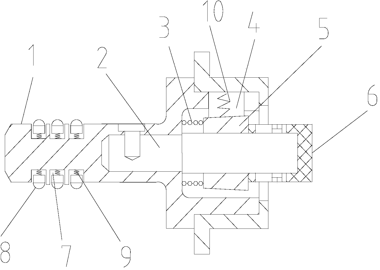
[0011] As shown in the figure, the expansion fixture includes clamp body 1, guide post 2, abdication spring 3, expansion block 4, taper sleeve 5, and top sleeve 6. The front end of clamp body 1 is provided with a groove 7, and in the groove 7 There is a protrusion 8, and the protrusion 8 and the groove 7 are connected by a spring 9, and the fixture is installed in the Morse taper hole at the front end of the lathe, and the protrusion 8 withstands the Morse taper hole under the action of the spring 9 to improve the The fastness of the connection between the clamp body 1 and the Morse taper hole reduces vibration. There is a cavity behind the clamp body 1. The guide post 2 is set in the clamp body 1. The abdication spring 3 and the taper sleeve 5 are set on the guide post 2. One end of the spring 3 is set on the inner wall of the cavity of the clamp body 1, and the other end is set on the front end of the taper sleeve 5. After the abdication spring 3 is processed and the top of t...


PUM


Abstract

The invention relates to the technical field of fixtures, in particular to an expansion fixture. The expansion fixture is characterized by comprising a fixture body, a guide column, a receding spring, expansion blocks, a taper sleeve and an abutting sleeve. A groove is formed in the front end of the fixture body, a protrusion is arranged in the groove, and the protrusion is connected with the groove through a spring; a cavity is formed behind the fixture body, the guide column is sleeved with the fixture body, and the guide column is sleeved with the receding spring and the taper sleeve; one end of the receding spring is arranged on the inner wall of the cavity of the fixture body, and the other end of the receding spring is arranged at the front end of the taper sleeve; the expansion blocks are arranged on the outer side of the taper sleeve and evenly inserted in the fixture body; the abutting sleeve is arranged at the rear end of the taper sleeve, and the front of the abutting sleeve is connected with the rear of the taper sleeve; receding elastic rings are arranged in the expansion blocks. The expansion fixture performs clamping conveniently and can reduce the resonance caused by clamping in the machining process and accelerate machining progress; besides, the expansion fixture is simple in structure and low in production cost.

Description

technical field [0001] The invention relates to the technical field of clamps, in particular to an expansion clamp. Background technique [0002] When turning the outer circle of sleeve workpieces, it is necessary to design a special fixture to assist in processing. The current fixture is more complicated when clamping, which affects processing, and the structure is complex, the production cost is high, and it is more complicated to replace the workpiece. . Contents of the invention [0003] In order to overcome the disadvantages of the above-mentioned technical problems, the present invention provides a clamping device which is convenient for clamping, can reduce resonance caused by clamping during processing, improves processing progress, and has a simple structure and low production cost. [0004] The technical scheme that solves the above-mentioned technical problem is as follows: [0005] The expansion fixture is characterized in that it includes a clamp body, a gui...

Claims


Application Information

Patent Timeline
IPC IPC(8): B23B31/40
CPCB23B31/404
Inventor 周黎仙
Owner CHANGZHOU CHANGOU METAL PROD
Learn More