Heating end and heater

A heating head and plug body technology, applied in the direction of induction heating, induction heating devices, etc., can solve the problems that affect the normal welding work, inconvenient use, insufficient heating head, etc.

A heating head and plug body technology, applied in the direction of induction heating, induction heating devices, etc., can solve the problems that affect the normal welding work, inconvenient use, insufficient heating head, etc.

CN107734730APending Publication Date: 2018-02-23高雄

Image

  • Heating end and heater
  • Heating end and heater
  • Heating end and heater

Examples


Embodiment Construction

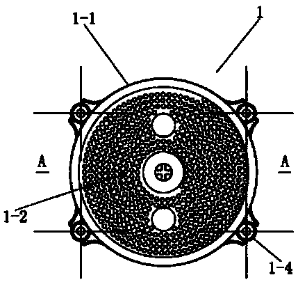
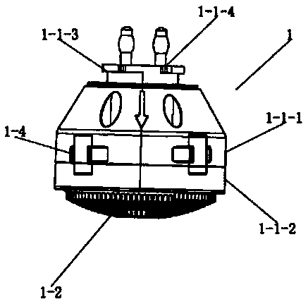
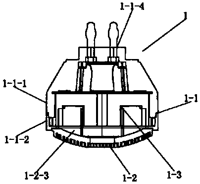
[0172] like Figure 1 to Figure 3 as shown,

[0173]This embodiment provides a heating head 1, which includes a casing 1-1, and a locking fitting part 1-1-3 is arranged on the back of the casing 1-1.

[0174] Various improvements as this embodiment are described below.

[0175] Such as Figure 20 to Figure 21 as shown,

[0176] The locking fitting part 1-1-3 includes a locking neck 1-1-3-1 and a locking head 1-1-3-2.

[0177] The locking neck 1-1-3-1 is an annular body extending backward from the rear surface of the housing 1-1.

[0178] The locking head 1-1-3-2 is a plurality of arc-shaped flanges extending radially outward from the rear edge of the outer surface of the locking neck 1-1-3-1.

[0179] The locking heads 1-1-3-2 are evenly distributed in the circumferential direction of the locking neck 1-1-3-1.

[0180] The arc length of the locking heads 1-1-3-2 is less than or equal to twice the arc distance between two adjacent locking heads 1-1-3-2.

[0181] There ar...


PUM


Abstract

The invention discloses a heating end and a heater. The heating end comprises a shell; a locking matching part is arranged behind the shell; the locking matching part comprises a locking neck and locking heads; the locking neck is a circular annular body which extends from the back part of the shell backwardly; the locking heads are multiple arc-shaped flanges which extend outwardly from the backpart of the outer side surface of the locking neck in the radial direction; the locking heads are uniformly distributed in the circumferential direction of the locking neck; the arc length of the locking heads is less than or equal to two times of the arc-shaped distance between two adjacent locking heads; the number of the locking heads is at least two; the number of the locking heads can be two,three or four; an opening is formed in the outer side of each locking head; and the opening is close to one end of each locking head. The heater comprises the heating end which is the abovementionedheating end. The connection firmness of the heating end can be greatly improved; an operator can hold a gun type electromagnetic heater by only one hand; and the heating end does not fall off easily,damage of the heating end caused by falling off can be avoided, and the heating end is very convenient to use.

Description

technical field [0001] The invention relates to a heating component and a heating device, in particular to a heating head and a heater. Background technique [0002] Heating and welding is a common processing method in industry and production fields, such as the plastic and rubber industry, transportation such as tunnel engineering, such as plastic film blowing machines, wire drawing machines or injection molding machines, pharmaceutical industry, energy and food industries, etc. Electromagnetic heating is a more popular heating method over the years. Since the ordinary heating coil heating method is usually a contact heat transfer heating method, the heat utilization rate is low, and only 30%-70% of its energy consumption is converted to work. Thermal energy, due to the phenomenon of cooling inertia at the same time as heating, if the heating is not timely, the heating time will be prolonged under the action of heat dissipation, while electromagnetic induction heating can u...

Claims


Application Information

Patent Timeline
23 Feb 2018
Publication
CN107734730A
IPC
H05B6/10
CPC
H05B6/10
Inventors
高雄