
Bidirectional guide post device

A guide post and guide technology, applied in the fields of machining and machine tool manufacturing, can solve the problems of short service life, difficult removal of guide posts, and easy errors.

Inactive Publication Date: 2015-02-25
JIANGSU TONGDA POWER TECH
View PDF3 Cites 0 Cited by
  • Summary
  • Abstract
  • Description
  • Claims
  • Application Information

AI Technical Summary

Problems solved by technology

The guide post and guide sleeve of this fixing method wear quickly and generate heat, which can easily cause deviations between the upper and lower molds, rapid decline in precision, and short service life. Secondly, when the mold plane is corrected, the guide post must be removed before machining, and repeated disassembly After that, it is easy to produce errors, which will cause the matching accuracy of the mold to decrease, fail to meet the requirements of installation accuracy, and cause the mold base and mold to be scrapped.
[0005] In the prior art, the structure of the guide post and guide sleeve used is a one-way guide post, and the end of the one-way guide post that is not equipped with a steel ball bushing is fixed on the bottom plate through a bolt connection, which cannot realize the convenient insertion and removal of the guide post. The guide post can only be taken out after bolting
Nowadays, the precision of the punching machine has been improved. After the mold is installed, the guide post will interfere with the processing of the workpiece. The guide post must be removed before the workpiece is processed. If the one-way guide post structure is used, the guide post is not easy to remove. A New Bidirectional Guide Column Device

Method used


Image

  • Bidirectional guide post device
  • Bidirectional guide post device

Examples


Embodiment Construction

[0022] The present invention is described in further detail now in conjunction with accompanying drawing. These drawings are all simplified schematic diagrams, which only illustrate the basic structure of the present invention in a schematic manner, so they only show the configurations related to the present invention.

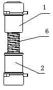
[0023] Such as figure 1 and figure 2 As shown, a two-way guide column device includes a guide column 3, an upper guide sleeve 1 and a lower guide sleeve 2, the upper guide sleeve 1 is fixed on the upper bottom plate of the mold, and the lower guide sleeve 2 is fixed on the mold On the lower bottom plate corresponding to the upper guide sleeve 1, a steel ball bushing 4 is sleeved on both ends of the guide post 3, and the inner diameter of the steel ball bushing 4 is the same as the diameter of the guide post 3. Adaptation, the two steel ball bushings 4 are respectively fixed on the two ends of the guide column 3 through the limit device, and the outer diamet...


PUM


Abstract

The invention discloses a bidirectional guide post device, comprising a guide post, an upper guide sleeve and a lower guide sleeve, wherein the upper guide sleeve is fixed on an upper bottom plate of a mold, the lower guide sleeve is fixed on a lower bottom plate of the mold and corresponds to the upper guide sleeve, two ends of the guide post are respectively sleeved with a steel ball bush, the inside diameter of the steel ball bush is matched with the diameter of the guide post, the two steel ball bushes are respectively fixed at two ends of the guide post through limiting devices, the outside diameters of the two steel ball bushes are respectively matched with the inside diameters of the upper guide sleeve and the lower guide sleeve, and a buffer device is sleeved on the guide post between the two steel ball bushes. Compared with the prior art, the bidirectional guide post device has the beneficial effects that the two ends of the guide post sleeved with the steel ball bushes are respectively inserted into the upper guide sleeve and the lower guide sleeve in use, so that an effect of bidirectional positioning is achieved; and the guide post of which the two ends are sleeved with the steel ball bushes can be easily extracted in nonuse, so the guide post is easy to detach.

Description

technical field [0001] The mold of the invention belongs to the fields of processing, machine tool manufacturing and the like, and relates to a bidirectional guide column device. Background technique [0002] In order to ensure accurate clamping and opening of the injection mold, a guiding mechanism must be set in the injection mold. The function of the guiding mechanism is guiding, positioning, and bearing certain lateral pressure. [0003] At present, in addition to the slider slide rail, the guide mechanism also has a guide pin and a guide post guide sleeve structure. The guide pin is used for low guiding accuracy requirements, and the guide post guide sleeve structure is used for high guiding accuracy requirements, such as progressive punching. The guide post and guide sleeve are used in the mold to position and guide the cutting edge of the mold, and the guide pin is used to position the workpiece. [0004] The guide posts and guide sleeves used in the existing mold b...

Claims


Application Information

Patent Timeline
IPC IPC(8): B29C33/30B29C45/26
Inventor 陈吴荣宋智峰王晓峰王岳
Owner JIANGSU TONGDA POWER TECH
Learn More