
Multi-shaft fluctuating rotation transmitting device and power generation device used for multi-shaft fluctuating rotation transmitting device

A torque-transmitting, single-axis technology, applied in the direction of transmission, gear transmission, belt/chain/gear, etc., can solve the problems of low working efficiency of generators, inability to generate electric energy, and reverse motion, etc., so as to facilitate implementation and promotion Use, low cost, and stable output rotation

Inactive Publication Date: 2015-02-25
HUNAN UNIV
View PDF6 Cites 2 Cited by
  • Summary
  • Abstract
  • Description
  • Claims
  • Application Information

AI Technical Summary

Problems solved by technology

[0003] In the commonly used power generation devices, the rotors are required to rotate stably in the same direction. When the drive shaft is not rotating stably, or even in the forward and reverse directions, if the rotor is directly connected to the drive shaft, the generator will work inefficiently, or even in the reverse direction. Motion is either locked or unable to generate power

Method used


Image

  • Multi-shaft fluctuating rotation transmitting device and power generation device used for multi-shaft fluctuating rotation transmitting device
  • Multi-shaft fluctuating rotation transmitting device and power generation device used for multi-shaft fluctuating rotation transmitting device
  • Multi-shaft fluctuating rotation transmitting device and power generation device used for multi-shaft fluctuating rotation transmitting device

Examples


specific Embodiment approach 1

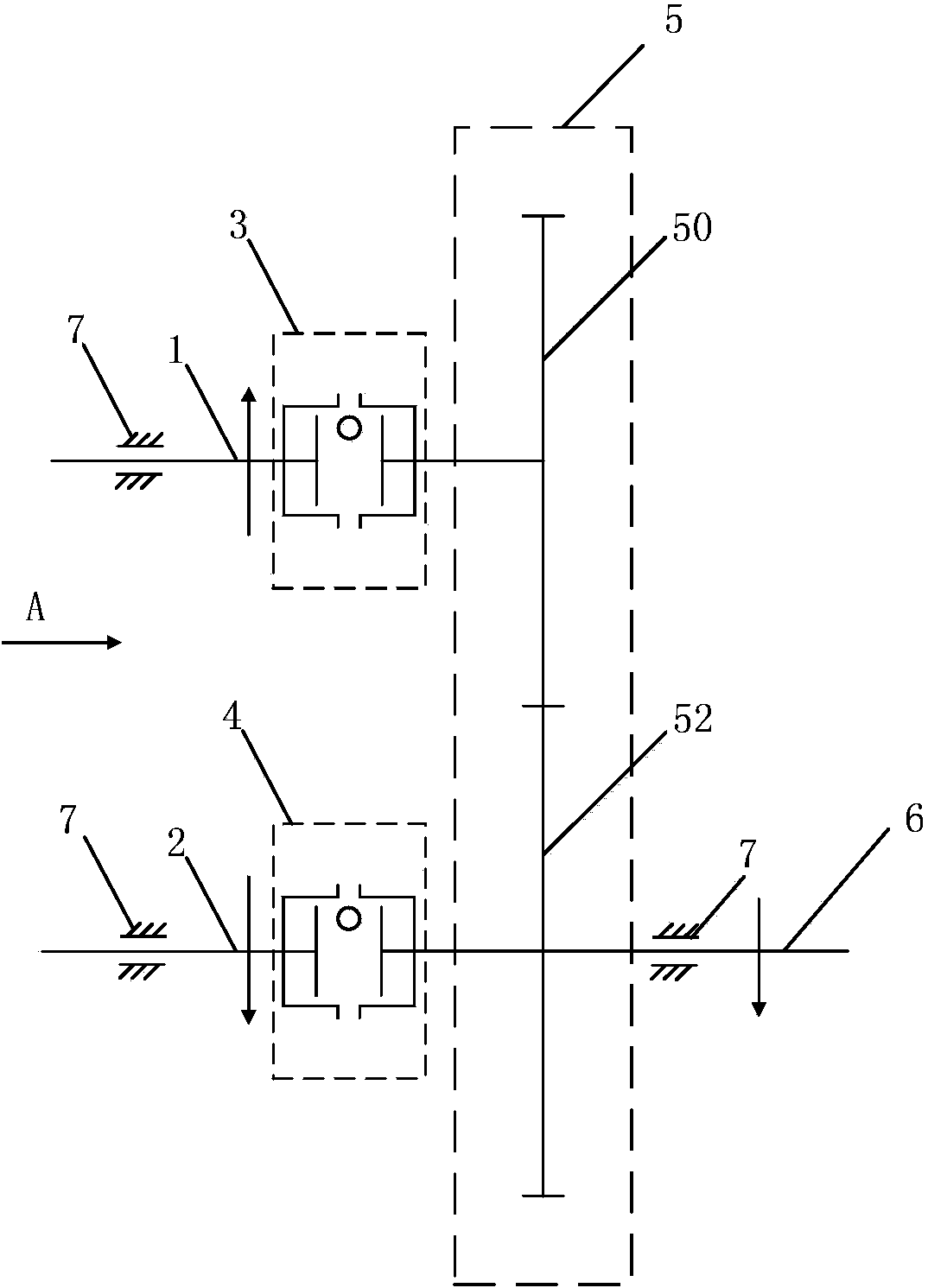
[0014] Specific implementation mode one: combine figure 1 This embodiment will be described. This embodiment includes a first drive shaft 1 , a first overrunning clutch 3 , a first gear 50 , a second drive shaft 2 , a second overrunning clutch 4 , a second gear 52 , and an output shaft 6 . The first gear 50 is connected with the first drive shaft 1 through the first overrunning clutch 3 , the second gear 52 is connected with the second drive shaft 2 through the second overrunning clutch 4 , and the first gear 50 is meshed with the second gear 52 . The rotation transmission directions of the two overrunning clutches are opposite, and the respective transmission directions are respectively shown by the arrows in the figure.

[0015] The working principle of this embodiment is:

[0016] When the first drive shaft 1 reaches the rotational speed of the first gear 50 along the direction shown in the figure (counterclockwise when viewed from direction A), the first overrunning clutc...

specific Embodiment approach 2

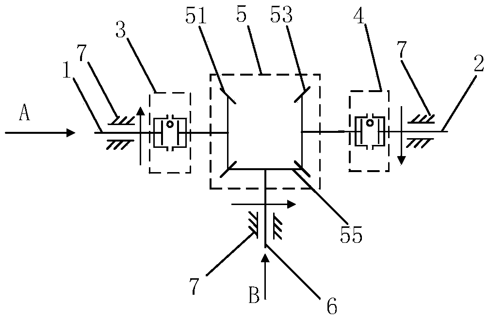
[0019] Specific implementation mode two: combination figure 2 Describe this embodiment, this embodiment includes the first drive shaft 1, the first overrunning clutch 3, the first bevel gear 51, the second drive shaft 2, the second overrunning clutch 4, the second bevel gear 53, and the third bevel gear 55 , Output shaft 6. The first bevel gear 51 is connected with the first drive shaft 1 through the first overrunning clutch 3, and the second bevel gear 53 is connected with the second drive shaft 2 through the second overrunning clutch 4. The first bevel gear 51 and the second bevel gear 53 are respectively It meshes with the third bevel gear 55 . The rotation transmission directions of the two overrunning clutches (3, 4) are opposite, and the respective transmission directions are respectively shown by arrows among the figures. Wherein the overrunning clutch can be replaced by the ratchet that plays the same direction of action.

[0020] The working principle of this embo...

specific Embodiment approach 3

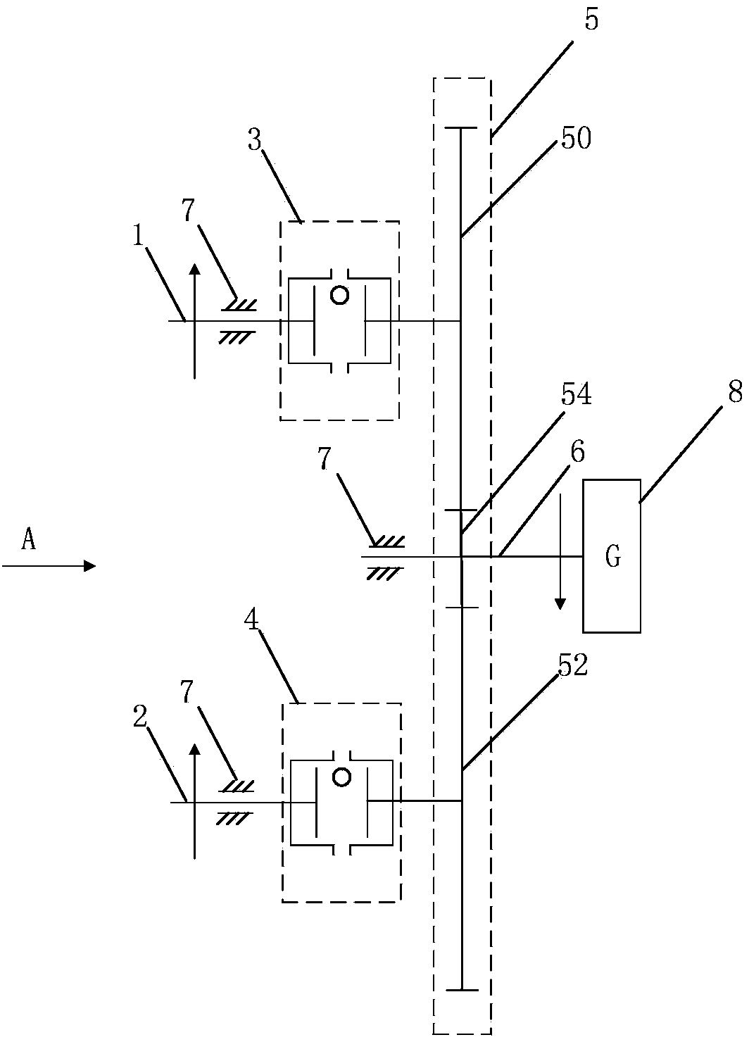
[0024] Specific implementation mode three: combination image 3 Describe this embodiment, this embodiment includes the first drive shaft 1, the first overrunning clutch 3, the first gear 50, the second drive shaft 2, the second overrunning clutch 4, the second gear 52, the third gear 54, the output shaft 6. Generator 5. The first gear 50 is connected with the first drive shaft 1 through the first overrunning clutch 3, the second gear 52 is connected with the second drive shaft 2 through the second overrunning clutch 4, and the first gear 50 and the second gear 52 are respectively connected with the third gear The 54 phases are meshed, and the output shaft is connected with the generator to drive the generator to generate electricity. The rotation transmission direction of the two overrunning clutches is the same, and the transmission direction is shown by the arrow in the figure. Wherein the overrunning clutch can be replaced by the ratchet that plays the same direction of a...


PUM


Abstract

The invention provides a device which converts multi-shaft rotation into single-shaft rotation and then converts kinetic energy into electric energy. The device mainly comprises driving shafts 1 and 2, overrunning clutches or ratchet mechanisms 3 and 4, a transmission gear set 5 and an output shaft 6. A first gear 50 is connected with the first driving shaft 1 through the first overrunning clutch 3. A second gear 52 is connected with the second driving shaft 2 through the second overrunning clutch 4. The first gear 50 is meshed with the second gear 52. If the device is provided with a plurality of driving shafts, an Nth gear is connected with an Nth driving shaft through an Nth overrunning clutch. All the gears are meshed with one another in a series connection or parallel connection mode to form the gear set 5. A certain gear shaft 6 in the gear set is used as the power output shaft for outputting kinetic energy. The device has the advantages of being simple in structure, high in reliability and capable of ensuring that the output shaft rotates stably, energy loss is lowered, and the energy transmission efficiency is improved on the condition that the driving shafts rotate unstably. When the device is used in cooperation with a power generation device, the device can make a power generator operate stably and promote the generating efficiency.

Description

technical field [0001] The invention relates to the field of machinery, and is especially suitable for converting multi-axis intermittent rotation or continuously changing rotation into a single-axis stable rotation output, and is especially suitable for simultaneously collecting multiple driving shafts and the rotating state of each driving shaft is not uniform and unstable. energy and use it for power generation. Background technique [0002] At present, the commonly used mechanical rotation transmission device is gear transmission. When multiple drive shafts transmit rotation to a single output shaft, the rotation of each drive shaft must cooperate with each other and be stable. If the rotation of each drive shaft cannot rotate at the speed corresponding to the transmission ratio Or when the rotation speed fluctuates greatly, the rotation transmission will interfere with each other, consume a lot of energy, the efficiency is low, and it is difficult to output stable rotat...

Claims


Application Information

Patent Timeline
Patent Type & Authority Applications(China)
IPC IPC(8): F16H1/22
CPCF16H1/22
Inventor 田凯东张农张邦基郑敏毅张雨
Owner HUNAN UNIV
Learn More