

Multifunctional flashlight
A multi-functional, flashlight technology, applied in the field of multi-functional flashlights, can solve the problems of inconvenient carrying and inconvenient maintenance, etc., and achieve the effect of reducing carrying storage space and reducing control actions
Inactive Publication Date: 2015-02-25
SUZHOU HUARI JINLING MACHINERY
View PDF4 Cites 0 Cited by
- Summary
- Abstract
- Description
- Claims
- Application Information
AI Technical Summary
Problems solved by technology
[0002] At present, most of the flashlights and maintenance tools used in the market are single tools. When using both for maintenance, the two tools must be controlled separately, which makes maintenance inconvenient. Sometimes maintenance requires a lot of tool types. It is very inconvenient and requires a large toolbox to store and carry
Method used
View moreImage
Smart ImageViewing Examples

Examples
Embodiment Construction
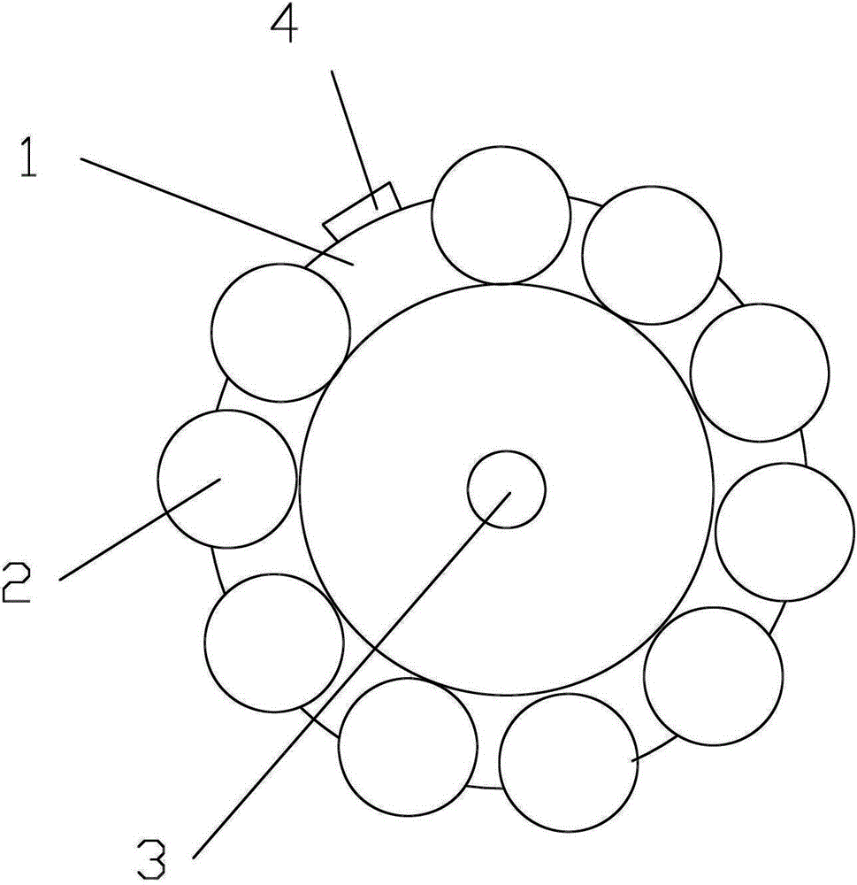
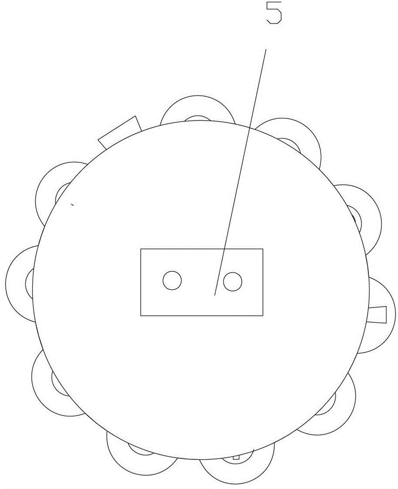
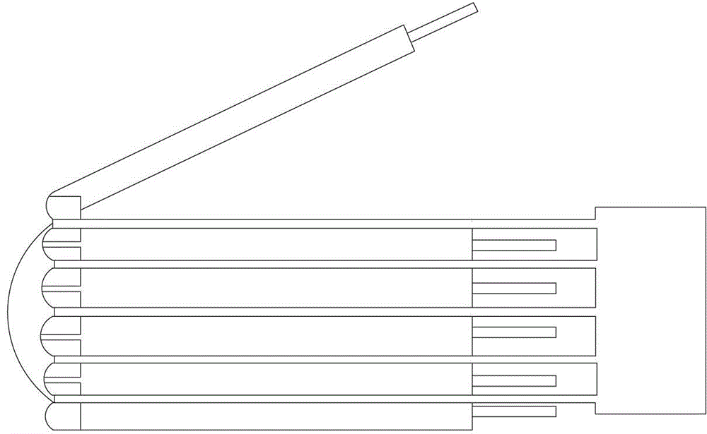
[0013] As shown in the figure, the multifunctional flashlight includes a shell 1, a lampshade 3, a tool bar 2 and a switch 4. The shell is designed in a cylindrical shape, and the lampshade is arranged on one end of the cylindrical shell. At the lampshade of the shell, the tool bar is half-buried on the shell in the same axial direction as the shell, the number of tool bars is 10, the switch is set on the side wall of the shell, and a charging port 5 is set at the bottom of the shell; Fold out the tool lever, turn on the switch, the light is facing the direction of tool operation.
Login to View More PUM
 Abstract
The invention discloses a multifunctional flashlight. The multifunctional flashlight comprises a cylindrical shell, a shade, tool rods and a switch, wherein the shade is arranged at one end of the cylindrical shell, one end of each tool rod is movably connected with the shell, the tool rods are half embedded into the shell in the same axial direction as the shell, and the switch is arranged on the sidewall of the shell. The multifunctional flashlight has the advantages that multiple models of maintenance tools are integrated on one device, so that unnecessary carrying and storage spaces for the maintenance tools are decreased; since the joint of the maintenance tools is positioned at the shade position, when being used, the tools are turned over to the same direction as light for operation, and unnecessary control actions can be decreased.
Description
technical field [0001] The invention relates to a multifunctional flashlight. Background technique [0002] At present, most of the flashlights and maintenance tools used in the market are single tools. When using both for maintenance, the two tools must be controlled separately, which makes maintenance inconvenient. Sometimes maintenance requires a lot of tool types. It is very inconvenient and needs to be stored and carried in a large toolbox. Contents of the invention [0003] Aiming at the deficiencies of the prior art, the invention provides a multifunctional flashlight with compact structure, scientific design and convenient use. [0004] The present invention realizes by following scheme: [0005] A multifunctional flashlight, including a shell, a lampshade, a tool rod and a switch. The shell is designed in a cylindrical shape. The lampshade is arranged at one end of the cylindrical shell. One end of the tool rod is movably connected with the shell. The tool rod a...
Claims
Login to View More Application Information
Patent Timeline
 IPC IPC(8): F21L4/00F21V33/00
Inventor向延海
OwnerSUZHOU HUARI JINLING MACHINERY