Method and system for improving detecting an empty catalyst housing

A catalytic converter and housing technology, applied in the field of catalytic converter housing removal, can solve problems such as violations and increased exhaust emissions, and achieve the effects of improving degradation assessment, improving performance levels, and improving robustness

Pending Publication Date: 2020-09-15
FORD GLOBAL TECH LLC
View PDF0 Cites 0 Cited by
  • Summary
  • Abstract
  • Description
  • Claims
  • Application Information

AI Technical Summary

Problems solved by technology

However, removal of catalyst substrates and coatings may violate government regulations and increase emissions of undesirable exhaust gases

Method used


Image

  • Method and system for improving detecting an empty catalyst housing
  • Method and system for improving detecting an empty catalyst housing
  • Method and system for improving detecting an empty catalyst housing

Examples


Embodiment Construction

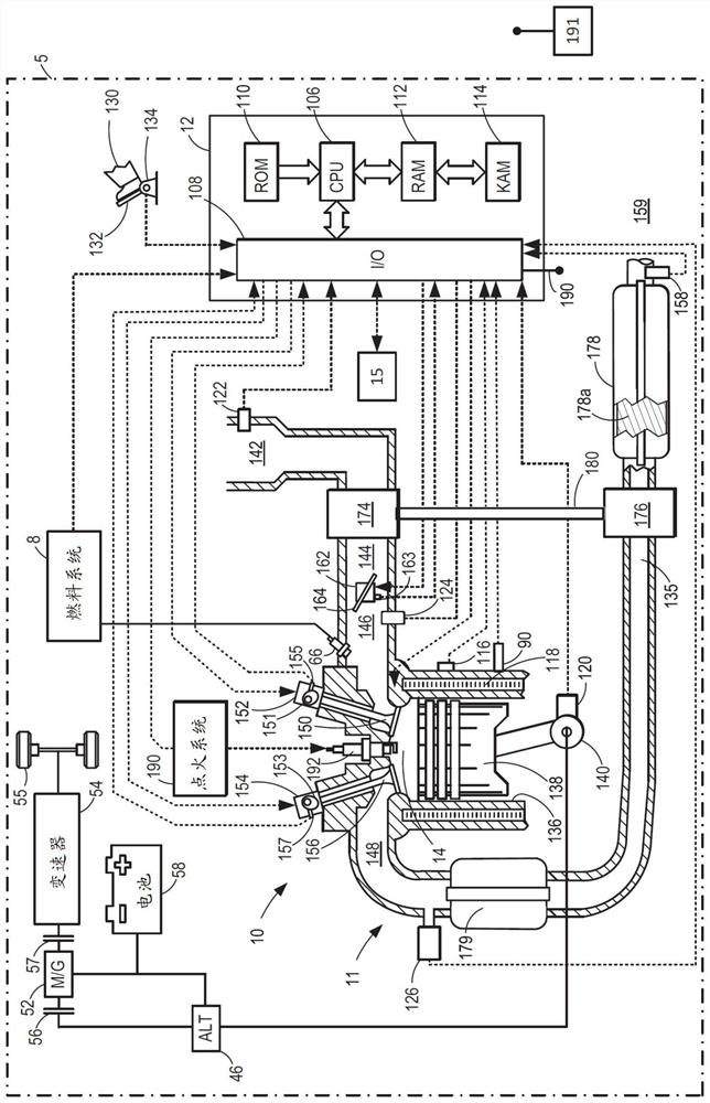
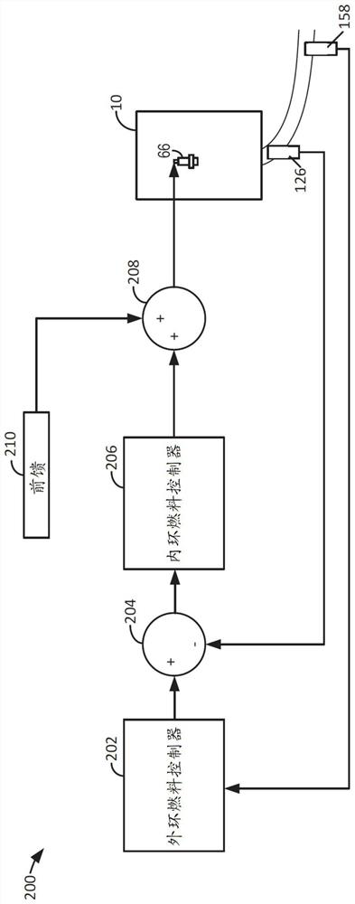
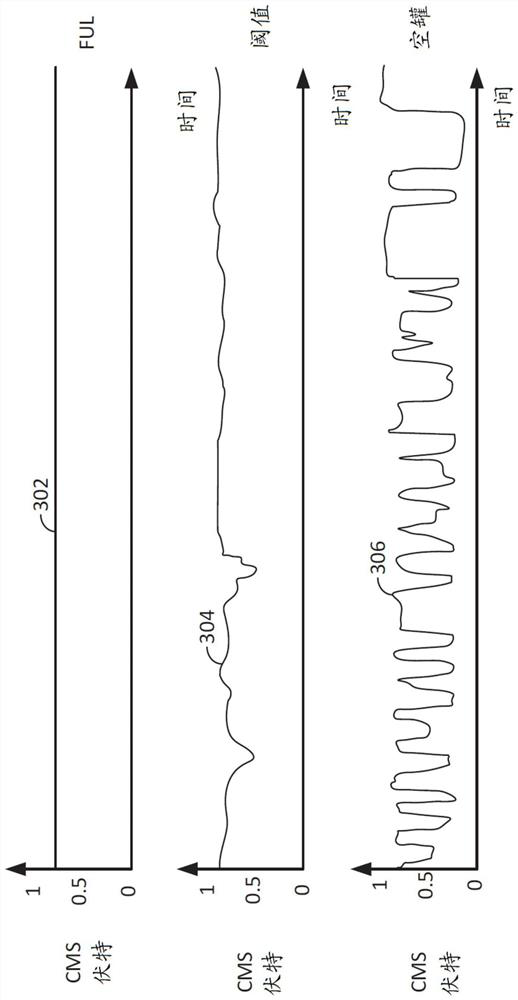
[0012] The following description relates to systems and methods for operating an engine, including diagnostics for monitoring performance of a catalyst. The engine can be figure 1 type shown. The engine may include a controller that regulates the amount of fuel injected into the engine. figure 2 A block diagram of an example fuel controller is shown in . image 3 Example output voltages of catalyst monitoring sensors exposed to gases flowing through different catalysts are shown in . Figure 4 Example sustained excitation metrics for different levels of catalyst degradation are shown in . Figure 5 A method for determining and compensating for an empty catalytic converter housing is shown in .

[0013] Now turning to the attached image, figure 1 An example of cylinder 14 of internal combustion engine 10 that may be included in vehicle 5 is depicted. The engine 10 includes a plurality of cylinders, figure 1 One cylinder is shown in , and the engine is controlled by an e...


PUM


Abstract

Methods and systems are provided for diagnosing the presence or absence of a catalyst substrate within a catalyst can or housing. The methods and systems described a persistence of excitation metric that is a basis for judging whether or not the catalyst can is empty. If it is determined that the catalyst can or housing is empty, mitigating control actions may be performed via a controller.

Description

technical field [0001] The present application relates to methods and systems for determining whether a catalyst has been removed from a catalyst housing located in an exhaust system of an internal combustion engine. Background technique [0002] Catalysts can be incorporated into the exhaust system of internal combustion engines to convert hydrocarbons and NOx into CO 2 , N 2 and H 2 O. Catalysts may consist of a substrate and a coating attached to the substrate. After the catalyst reaches a threshold temperature, the exhaust gas flowing through the substrate can be converted to CO 2 , N 2 and H 2 O. The efficiency with which a catalyst converts exhaust gas may also depend on the past history of exhaust gas that has flowed through the catalyst and the current chemical state within the catalyst. Although many vehicle owners believe that converting exhaust into CO 2 , N 2 and H 2 O is a useful process and it is desirable to comply with government regulations, but s...

Claims


Application Information

Patent Timeline
Patent Type & Authority Applications(China)
IPC IPC(8): F01N11/00
CPCF01N11/00F01N11/007F02D11/105F02D11/107F02D41/0002F02D41/0295F02D41/40F02D2250/26Y02T10/40F01N2550/02F01N2550/24F01N2560/025F01N2900/14F01N2900/1622
Inventor 马里奥·桑蒂洛安德鲁·巴尼亚斯科姆德詹·扬科维奇
Owner FORD GLOBAL TECH LLC
Why Eureka
Try Eureka