
Outer circulation heat radiation structure of embedded induction cooker

A heat dissipation structure and induction cooker technology, which is applied in the field of kitchen stoves, can solve the problems that the heat of the induction cooker cannot be discharged outside the cabinet, the heat dissipation function of the embedded induction cooker is not ideal, and the safety and reliability of the induction cooker are affected, so as to reduce the unsatisfactory heat dissipation function , Improved heat dissipation and ventilation effect, simple structure

Inactive Publication Date: 2015-02-25
火曌
View PDF0 Cites 0 Cited by
  • Summary
  • Abstract
  • Description
  • Claims
  • Application Information

AI Technical Summary

Problems solved by technology

[0003] Although the induction cooker has various conveniences, it also has some unsatisfactory places. The heat dissipation function of the current embedded induction cooker is not ideal, because the ventilation and heat dissipation structure adopted is an internal circulation cooling structure.
That is, the fan at the bottom of the embedded induction cooker body absorbs air from the closed cabinet, and then the air circulates inside the furnace body for a week and then is discharged from the air outlet behind the furnace body to the closed cabinet, so that due to the cooling air of the induction cooker It has been circulating in the closed cabinet, so that the heat generated by the induction cooker cannot be discharged outside the cabinet, resulting in excessive temperature of the furnace, which seriously affects the safety and reliability of the induction cooker

Method used


Image

  • Outer circulation heat radiation structure of embedded induction cooker

Examples


Embodiment Construction

[0016] The specific embodiments of the present invention will be further described below in conjunction with the accompanying drawings.

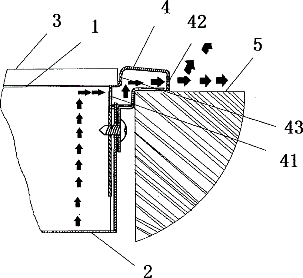
[0017] Such as figure 1 As shown, the present invention includes a built-in induction cooker panel 1, a bottom shell 2, and an air circulation channel bracket 4 is arranged between the built-in induction cooker panel 1 and the bottom shell 2, and the air circulation channel bracket 4 is made of a hard metal material. The air circulation channel support 4 is arranged around the embedded induction cooker panel 1, the air circulation channel support 4 is a hollow cavity, and its inner edge is provided with a support step 43 supporting the embedded induction cooker panel 1, and the embedded induction cooker panel 1 Located on the support step 43 and the joint between the built-in induction cooker panel 1 and the support step 43 of the air circulation channel bracket is provided with a sealing strip 3, the inner side of the support step 43 is pro...


PUM


Abstract

The invention discloses an outer circulation heat radiation structure of an embedded induction cooker. The structure comprises an embedded induction cooker panel and a bottom shell; an air circulation channel support is arranged between the embedded induction cooker panel and the bottom shell; the air circulation channel support is arranged to surround the embedded induction cooker panel and is a hollow cavity; support steps that bear the embedded induction cooker panel are arranged in the inner edge of the air circulation channel support; embedded induction cooker panel is arranged on the support steps; the inner side of the support steps is provided with an opening that communicates with the inner of the bottom shell; the lower part of the air circulation channel support is connected to the bottom shell, and air outlets are distributed on the external edge of the air circulation channel support. The external edge of the air circulation channel support is placed on the surface of a hearth at first, and then a stove is embedded into the support. The upper part of the hearth surface is provided with an air outlet, which can effectively induce the air flow direction in the stove so as to achieve outer circulation.

Description

technical field [0001] The invention relates to a heat dissipation structure, specifically a heat dissipation structure of an electromagnetic cooker, more specifically an outer circulation heat dissipation structure of an embedded electromagnetic cooker, and belongs to the technical field of kitchen ranges. Background technique [0002] Induction cooker, also known as induction cooker, is the product of the modern kitchen revolution. It does not need open flame or conduction heating to generate heat directly at the bottom of the pot, so the thermal efficiency has been greatly improved. It is a kind of high-efficiency and energy-saving kitchen utensils, which is completely different from all traditional fire or non-fire conduction heating kitchen utensils. An induction cooker is an electric cooking appliance made using the principle of electromagnetic induction heating. It is composed of high-frequency induction heating coil (ie excitation coil), high-frequency power convers...

Claims


Application Information

Patent Timeline
IPC IPC(8): F24C15/00F24C7/00
CPCF24C15/006H05B6/12
Inventor 火曌
Owner 火曌
Learn More