
Ventilation and heat dissipation device for elevator

A ventilation and heat dissipation, elevator technology, applied in the field of elevators, can solve problems such as difficult disassembly and cleaning of heat dissipation devices, influence on fan rotation, high elevator shaft height, etc., and achieve the effects of increasing heat dissipation and ventilation, easy disassembly and assembly, and increasing brightness

Inactive Publication Date: 2021-03-09
湖南东升电梯工程有限公司
View PDF0 Cites 0 Cited by
  • Summary
  • Abstract
  • Description
  • Claims
  • Application Information

AI Technical Summary

Problems solved by technology

[0003] In summer, when there are many people in the elevator car, the temperature is high, and electric fans are usually used to cool down the temperature. The existing elevator ventilation and heat dissipation devices have deficiencies. When moving up and down, dust enters the interior of the elevator car and falls on the fan. After a long time accumulation, a thick layer of dust adheres to the fan, which affects the rotation of the fan, and the cooling device is difficult to disassemble and clean.

Method used


Image

  • Ventilation and heat dissipation device for elevator
  • Ventilation and heat dissipation device for elevator
  • Ventilation and heat dissipation device for elevator

Examples


Embodiment 1

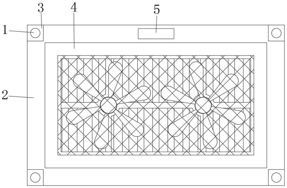
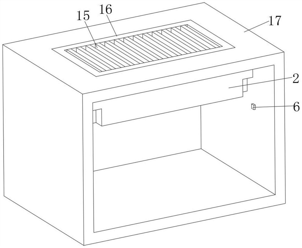
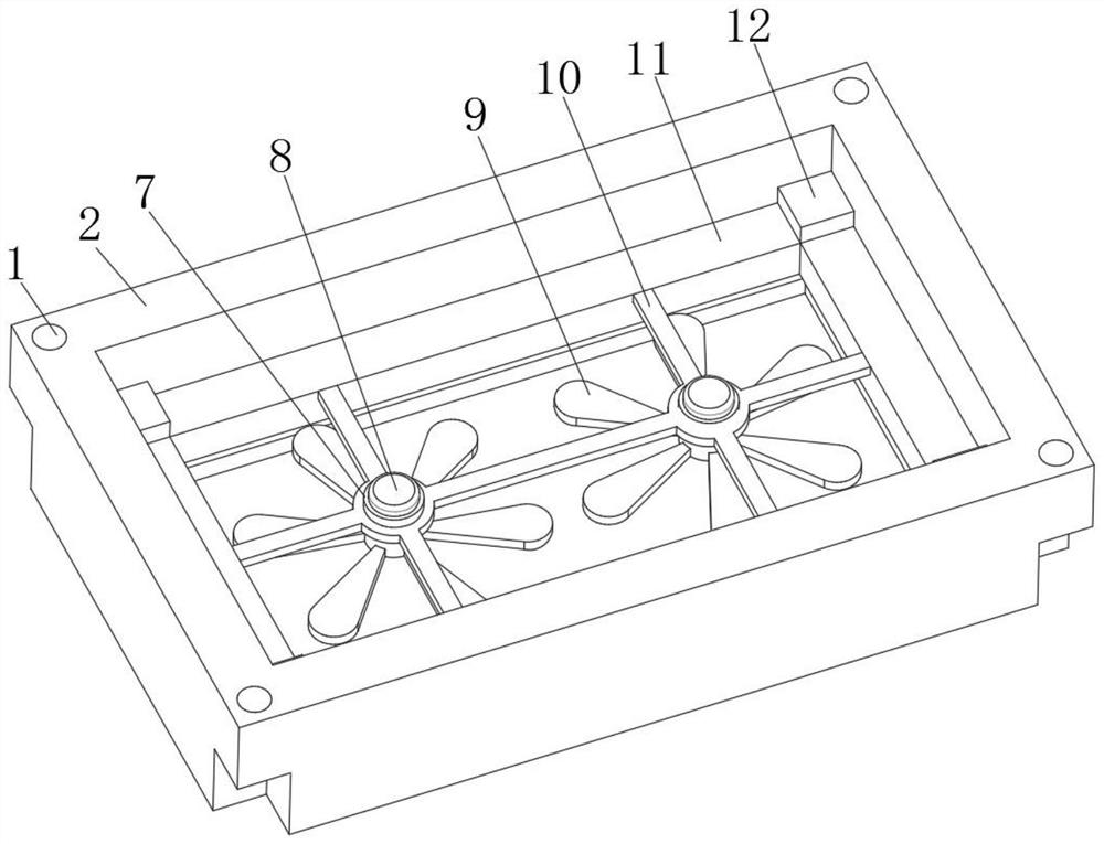
[0030] refer to Figure 1-3 , a ventilation and cooling device for an elevator, comprising an elevator car 17, the top inner wall of the elevator car 17 is fixed with a cooling box 2 by screws, and the inner wall of the cooling box 2 is fixed with a mounting plate 12 by screws near the four corners, and the mounting plate 12 The outer wall of the bottom of the bottom is fixed with a mounting frame 11 by screws, and the inner wall of the mounting frame 11 is fixed with a mounting frame 10 by screws, and the inside of the mounting frame 10 is fixed with two symmetrically distributed mounting tubes 7 by screws, and the circumferential inner wall of the mounting tube 7 The motor 8 is fixed by screws, and the top of the output shaft of the motor 8 is fixed with the fan blade 9 by screws. When the device is used for a long time, a thick layer of dust is attached to the surface. Remove the installation frame 11, the motor 8, and the fan blade 9 in sequence. The device is cleaned, the...

Embodiment 2

[0038] refer to Figure 4, a ventilation and cooling device for an elevator, comprising an elevator car 17, the top inner wall of the elevator car 17 is fixed with a cooling box 2 by screws, and the inner wall of the cooling box 2 is fixed with a mounting plate 12 by screws near the four corners, and the mounting plate 12 The outer wall of the bottom of the bottom is fixed with a mounting frame 11 by screws, and the inner wall of the mounting frame 11 is fixed with a mounting frame 10 by screws, and the inside of the mounting frame 10 is fixed with two symmetrically distributed mounting tubes 7 by screws, and the circumferential inner wall of the mounting tube 7 The motor 8 is fixed by screws, and the top of the output shaft of the motor 8 is fixed with the fan blade 9 by screws. When the device is used for a long time, a thick layer of dust is attached to the surface. Remove the installation frame 11, the motor 8, and the fan blade 9 in sequence. The device is cleaned, the lo...


PUM


Abstract

The invention discloses a ventilation and heat dissipation device for an elevator. The ventilation and heat dissipation device for the elevator comprises an elevator car, wherein a heat dissipation box is fixed to the inner wall of the top of the elevator car; mounting plates are fixed to the positions, close to the four corners, of the inner wall of the heat dissipation box; a mounting frame is fixed to the outer walls of the bottoms of the mounting plates; a mounting rack is fixed to the inner wall of the mounting frame; two symmetrically-distributed mounting cylinders are fixed in the mounting rack; motors are fixed to the inner walls of the circumferences of the mounting cylinders; fan blades are fixed to the top ends of output shafts of the motors; and a protective net is fixed to theposition, close to the bottom, of the inner wall of the heat dissipation box. According to the ventilation and heat dissipation device for the elevator provided by the invention, through the arrangement of the heat dissipation box, the mounting plate, the mounting frame, the mounting rack, the mounting cylinders, the motors and the fan blades, after the device is used for a long time, a layer ofthick dust is attached to the surface, the mounting frame, the motors and the fan blades are sequentially disassembled, and the device is cleaned, so that the load of the fan blades is reduced, the heat dissipation and ventilation effects of the device are improved, and the device is cleaner, easy to disassemble, and convenient to use by people.

Description

technical field [0001] The invention relates to the technical field of elevators, in particular to a ventilation and cooling device for elevators. Background technique [0002] Elevator is a kind of vertical elevator powered by electric motor, equipped with box-shaped gondola, which is used for multi-storey buildings to take people or carry goods. There is also a step type, and the tread plate is installed on the crawler belt to run continuously, commonly known as an escalator or a moving walk. Fixed lifting equipment serving specified floors. A vertical lift has a car that runs between at least two vertical columns of rigid guide rails. The size and structure of the car are convenient for passengers to enter and exit or to load and unload goods. It is customary to use elevator as a general term for vertical transportation in buildings regardless of its driving mode. According to the speed, it can be divided into low-speed elevators (below 1 m / s), fast elevators (1-2 m / s...

Claims


Application Information

Patent Timeline
IPC IPC(8): B66B11/02F21V21/00F24F7/007
CPCB66B11/0226B66B11/0233B66B11/024F21V21/00F24F7/007
Inventor 颜旭阳
Owner 湖南东升电梯工程有限公司
Learn More