
Medical wristband beeper

A pager and wristband technology, which is applied in the field of medical wristband pagers, can solve problems such as inconvenient use, lack of call function, failure, etc.

Inactive Publication Date: 2015-02-25
SHAANXI YIFU BEAUTY THERAPY TECH
View PDF0 Cites 2 Cited by
  • Summary
  • Abstract
  • Description
  • Claims
  • Application Information

AI Technical Summary

Problems solved by technology

[0004] The purpose of the present invention is to overcome the problem of inconvenient use or failure caused by the fixed scope of use of the existing medical calling system and the defect that the existing medical wristbands are portable but do not have a calling function

Method used


Image

  • Medical wristband beeper

Examples


Embodiment 1

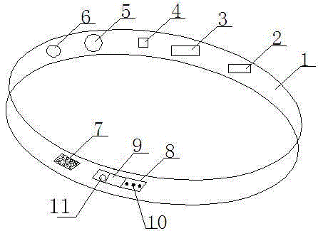
[0012] In order to solve the problem of inconvenience or failure caused by the fixed use range of the existing medical calling system and the defect that the existing medical wristband is portable, but does not have the calling function, this embodiment provides a figure 1 The medical wristband pager shown includes a wristband 1, and also includes a power circuit module 2, a GPRS module 3, a battery compartment 4 for installing batteries, a wireless calling module 7, a control panel 8 and installation on the wristband 1. The laser module 11 on the control panel 8 and the power circuit module 2 are electrically connected to the wireless call module 7, the GPRS module 3, the battery compartment 4, the control panel 8 and the laser module 11, respectively. By attaching the wireless call function to the medical wristband, it is convenient for patients to initiate calls anytime and anywhere. The GPRS module can be used to locate the patient and find the patient in time. The laser mod...

Embodiment 2

[0014] In order to further better detect the patient’s physical condition and facilitate timely rescue, this embodiment adds a heart rate detection module 5 to the wristband 1, which is electrically connected to the power circuit module 2 and the wireless calling module 7. In an unfavorable situation, the heart rate detection module 5 sends a distress signal to the receiver worn by the medical staff or the host of the medical care center through the wireless calling module 7.

Embodiment 3

[0016] In order to view the patient's information (such as number, ward, condition, contact, etc.) at any time, this embodiment adds a memory chip 6 for storing patient information to the wristband, which is electrically connected to the power circuit module 2 and the control panel 8 respectively. , The control panel 8 includes a display screen 9, a read button, and a call button 10.

[0017] In summary, it is not difficult to see that the medical wristband pager provided in this embodiment attaches the wireless calling function to the medical wristband, which is convenient for patients to initiate calls anytime and anywhere. The patient can be positioned through the GPRS module, which is convenient Find the patient in time, and you can remotely understand the patient's physical condition at any time through the heart rate detection module.


PUM


Abstract

The invention provides a medical wristband beeper which comprises a wristband, a wireless calling module, a GPRS module, a power circuit module, a battery bin, a control panel and a laser module, wherein the wireless calling module, the wireless calling module, the GPRS module, the power circuit module, the battery bin and the control panel are arranged on the wristband, the battery bin is used for mounting a battery, and the laser module is mounted on the control panel. The power circuit module is connected with the wireless calling module, the GPRS module, the battery bin, the control panel and the laser module respectively. The medical wristband beeper has the advantages that a wireless calling function is added to the medical wristband, a patient can start calling anytime and anywhere, locating of the patient can be achieved through the GPRS module so that the patient can be found in time, the physical condition of the patient can be known remotely through a heart rate detection module, and the medical wristband beeper can provide illumination for the patient at night.

Description

Technical field [0001] The invention relates to a medical wristband calling device, in particular to a wristband calling device wirelessly connected with an existing hospital monitoring system. Background technique [0002] At present, the paging system used in hospitals generally includes a call terminal installed in the ward and a host installed in the nurse station. The call terminal communicates with the host, so that the patient can call the doctor or nurse. However, the call terminal is installed at the bedside. When the patient encounters an emergency when the patient is weak or the escort is absent, or the patient is not in the ward, this call system fails. [0003] In order to distinguish between patients, the hospital wears a wristband to each patient. This kind of wristband generally only numbers the patients through the digital code on it, and has no other functions. Summary of the invention [0004] The purpose of the present invention is to overcome the problems of in...

Claims


Application Information

Patent Timeline
Patent Type & Authority Applications(China)
IPC IPC(8): G08B21/02G08B25/10A61B5/0245
CPCG08B25/016A61B5/0245
Inventor 赵宏丽
Owner SHAANXI YIFU BEAUTY THERAPY TECH
Learn More