
A Design Method of Near-field Uniform Beam Millimeter-Wave Antenna

A millimeter-wave antenna and design method technology, applied in antennas, antenna arrays, calculations, etc., can solve problems such as short wavelength of electromagnetic waves, complex beam and energy distribution, and energy oscillation

Active Publication Date: 2017-03-22
中久安特装备有限公司
View PDF2 Cites 0 Cited by
  • Summary
  • Abstract
  • Description
  • Claims
  • Application Information

AI Technical Summary

Problems solved by technology

However, in the field of millimeter-wave antenna technology, due to the short wavelength of electromagnetic waves (1mm to 10mm), many applications (such as: millimeter-wave plasma heating, millimeter-wave imaging / detection, millimeter-wave short-range communication, radio frequency identification, etc.) In the near-field area of ​​the antenna, due to the superposition of Fresnel diffraction, the distribution of beams and energy in the near-field area is very complicated, and the energy fluctuates violently with the change of distance. It is no longer possible to simply use the pattern to describe and design its distribution law
In the above applications, it is hoped that the near-field millimeter-wave beam will be relatively uniform within a certain distance range, but there is no effective method to design a near-field uniform beam millimeter-wave antenna

Method used


Image

  • A Design Method of Near-field Uniform Beam Millimeter-Wave Antenna
  • A Design Method of Near-field Uniform Beam Millimeter-Wave Antenna
  • A Design Method of Near-field Uniform Beam Millimeter-Wave Antenna

Examples


specific Embodiment

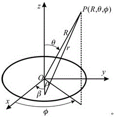
[0061] Adopt the design method described in the present invention, designed a set of antennas that are used for the proof of principle experimental research, the design goal is:

[0062] a. Working frequency: 95GHz;

[0063] b. Diameter Ф300mm;

[0064] c. Feed-in power: 45mW;

[0065] d. Uniform beam center power density: 2.1mW / cm2;

[0066] e. The distance range of the uniform beam: 1.2m ~ 4.0m.

[0067] The near-field shaped beam synthesis method is used to synthesize the mouth surface of Ф300mm, and the comprehensive target is that the axial power density within the distance range of 1.2m to 4.0m is about 2.1mW / cm 2 . A given mouth-face amplitude distribution such as Figure 7 As shown, the mouth-surface amplitude is a parabolic distribution, and the edge illumination is approximately 0.

[0068] The obtained oral-face phase distribution is as Figure 8 As shown in , it can be seen that the distribution of the phase at the center of the aperture is similar to that o...


PUM


Abstract

The invention belongs to the technical field of millimeter wave antennas. The problems that near-field wave-beam distribution fluctuation of a millimeter aperture antenna in various application fields is violent and goes against practical application, and an efficient uniform-wave-beam millimeter antenna designing method does not exist at present are solved. By the method for designing the near-field uniform-wave-beam millimeter wave antenna, a millimeter wave antenna with uniform wave beams in a near-field region can be designed step by step. The method for designing the near-field uniform-wave-beam millimeter wave antenna can be widely used for fields with beamforming requirements on near-field wave beam distribution such as millimeter wave plasma heating antennas, millimeter short-range communication, radiofrequency recognition and millimeter wave imaging.

Description

technical field [0001] The field of millimeter wave antennas of the present invention specifically refers to a method for designing a near-field uniform beam millimeter wave antenna. Background technique [0002] The far-field energy and beam distribution characteristics of the antenna are only related to the direction, so the pattern of the far-field energy distribution can be described. However, in the field of millimeter-wave antenna technology, due to the short wavelength of electromagnetic waves (1mm to 10mm), many applications (such as: millimeter-wave plasma heating, millimeter-wave imaging / detection, millimeter-wave short-range communication, radio frequency identification, etc.) In the near-field area of ​​the antenna, due to the superposition of Fresnel diffraction, the distribution of beams and energy in the near-field area is very complicated, and the energy fluctuates violently with distance. It is no longer possible to simply use the pattern to describe and des...

Claims


Application Information

Patent Timeline
Patent Type & Authority Patents(China)
IPC IPC(8): H01Q21/00G06F17/50
Inventor 徐刚余川孟凡宝屈劲陈世韬施美友薛长江
Owner 中久安特装备有限公司
Learn More