
Shield sleeve and shielding end element comprising a shield sleeve

A technology of shielding sleeves and sleeves, which is applied to the parts, electrical components, coupling devices and other directions of the connecting device, can solve the problem of high contact impedance

Active Publication Date: 2015-02-25
TE CONNECTIVITY GERMANY GMBH
View PDF7 Cites 17 Cited by
  • Summary
  • Abstract
  • Description
  • Claims
  • Application Information

AI Technical Summary

Problems solved by technology

In addition, the contact resistance is relatively high

Method used


Image

  • Shield sleeve and shielding end element comprising a shield sleeve
  • Shield sleeve and shielding end element comprising a shield sleeve
  • Shield sleeve and shielding end element comprising a shield sleeve

Examples


Embodiment Construction

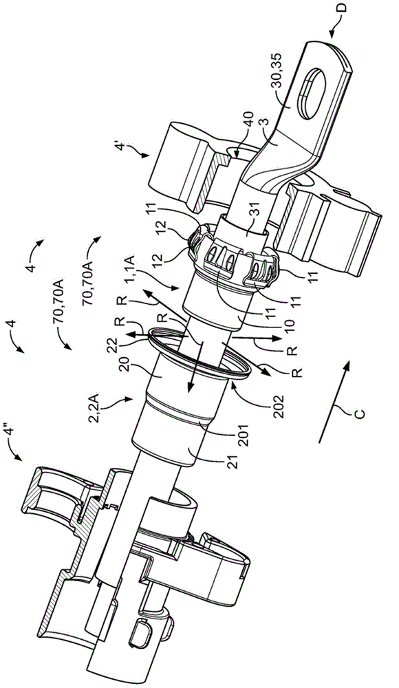
[0040] figure 1 is a perspective view of a first embodiment 1A of a shielding sleeve 1 according to the invention and a first embodiment 2A of a crimping sleeve 2 according to the invention, a cable 3 and a housing 4 comprising a first housing Part 4' and a second housing part 4". The housing parts 4', 4" are shown in partial cutaway. exist figure 1 A pre-assembled state is shown in where connections have not yet been made between the individual elements. The shielding sleeve 1 and the crimping sleeve 2 are assembled on the cable 3 and arranged forward and backward along the direction C of the cable.

[0041] The cable 3 comprises an inner conductor 30, an intermediate insulating material 31 and a cable shield (not shown) located outside the intermediate insulating material 31 and surrounded by an outer insulation (not shown). At the distal end D of the conductor 30 of the cable 3 is arranged a contact portion 35 for making contact with another element (not shown).

[0042...


PUM


Abstract

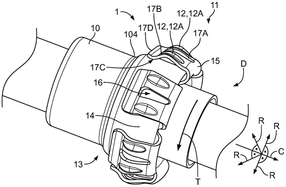
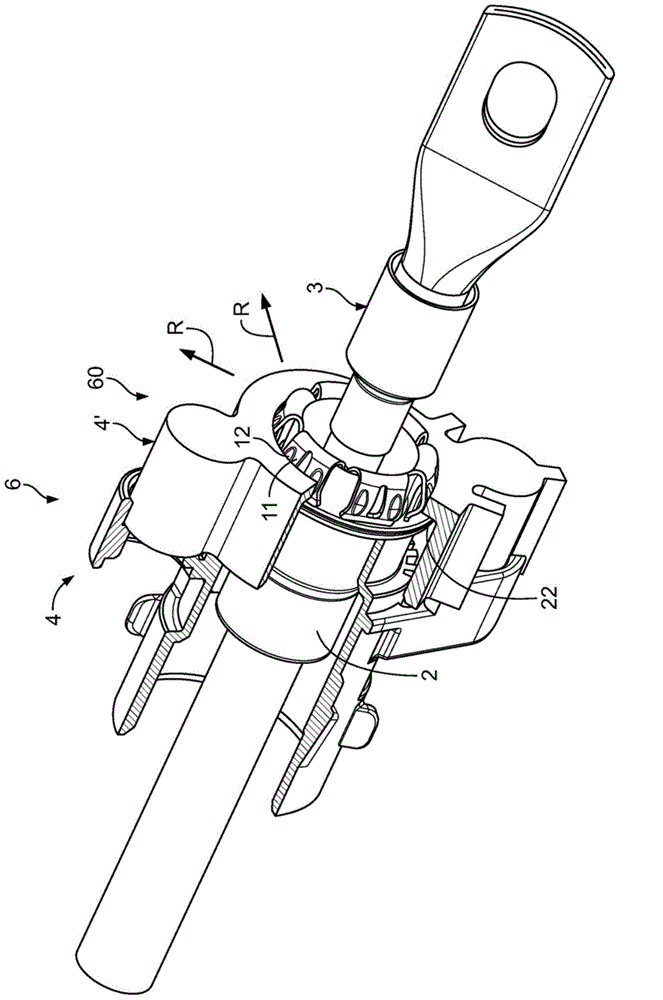
The invention relates to a shield sleeve (1) for producing an electrical connection between a cable shield and a metal housing portion (4') of a connection element. The invention further relates to a shielding end element (70) comprising such a shield sleeve (1) and a crimp sleeve (2) which is constructed so as to be able to be fitted over the shield sleeve (1). Shield sleeves (1) are known from the prior art. Shield sleeves having a cylindrical sleeve member (13) in which a circular ring is arranged at one end, said ring extending perpendicularly relative to the cylinder axis and consequently perpendicularly relative to the direction of the cable, are widespread. With such shield sleeves (1), the contact force and consequently the contact resistance are highly dependent on the connection and the force between the housing portions of the connection element. The contact resistance is further relatively high. An object of the present invention is to provide a shield sleeve (1) which ensures secure and consistent contact resistance which is substantially independent of the forces between the housing portions (4' 4'') of the connection element. The object is achieved according to the invention by a shield sleeve (1) which comprises a rotationally symmetrical sleeve member (13), at one end (D) of which there is arranged at least one radially protruding contact flap (11) which can be resiliently redirected in a radial direction (R), the contact flap (11) having at least one contact location (12) which protrudes in a radial direction with respect to the sleeve member (13). A shielding end element (70) according to the invention comprises a shield sleeve (1) according to the invention and a crimp sleeve (2) which is constructed so as to be able to be fitted over the shield sleeve (1).

Description

technical field [0001] The invention relates to a shielding sleeve for forming an electrical connection between a metal housing part of a connection element and a cable shield. Furthermore, the invention relates to a shielding end element comprising such a shielding sleeve and a crimping sleeve configured to be fitted onto the shielding sleeve. Background technique [0002] Shielding sleeves are known in the prior art. Shielding sleeves with a cylindrical sleeve member are widely used, wherein at one end of the sleeve member a circular ring is arranged, said ring extending perpendicularly with respect to the cylinder axis and thus perpendicularly with respect to the cable direction. The cable shield is arranged on the cylindrical sleeve member, and is fixed by means of a crimping sleeve fitted on the sleeve member and the cable shield and crimped thereto, whereby an electrical connection is made between the cable shield and the shield sleeve. touch. In order to also be ab...

Claims


Application Information

Patent Timeline
Patent Type & Authority Applications(China)
IPC IPC(8): H01R9/05H01R13/6582
CPCH01R13/6582H01R9/0527H01R4/646H01R4/48
Inventor M.利斯廷G.托特A.德雷斯尔F.凯尼
Owner TE CONNECTIVITY GERMANY GMBH
Learn More