Position detection device and method thereof

A detector and potential technology, applied in the input/output process of data processing, instruments, electrical digital data processing, etc., can solve the problems of increasing the density of wires, reducing the frequency of detection, and inaccurate overlapping points, etc., to achieve performance-enhancing effect

Active Publication Date: 2011-04-20
EGALAX EMPIA TECH INC
View PDF5 Cites 11 Cited by
  • Summary
  • Abstract
  • Description
  • Claims
  • Application Information

AI Technical Summary

Problems solved by technology

[0003] However if figure 1 As shown, when a finger touches, it may cause a group of overlapping points to be pressed at the same time. During the detection process, the signal of the lower electrode layer wire to be detected later will become smaller. Therefore, it is necessary to target phases at different positions. Different comparison values ​​are given to overlapping points, so that it can still distinguish whether it is pressed or not when the signal is small
However, such a solution may still be inaccurate because there are too many intersecting points that have been pressed before. Obviously, the establishment and storage of the comparison values ​​of each intersecting point need to spend a lot of cost, but it cannot guarantee accuracy. Spend
In addition, when the resolution requirement is relatively high, the density of the wire must be increased, and the detection frequency must be reduced relatively.
[0004] This shows that above-mentioned prior art obviously has inconvenience and defective, and extremely waits to be further improved
In order to solve the above-mentioned problems, the relevant manufacturers have tried their best to find a solution, but no suitable design has been developed for a long time, and there is no suitable structure and method for general products and methods to solve the above-mentioned problems. This is obviously a problem that relevant industry players are eager to solve

Method used


Image

  • Position detection device and method thereof
  • Position detection device and method thereof
  • Position detection device and method thereof

Examples


Embodiment Construction

[0099] In order to further explain the technical means and effects of the invention to achieve the intended purpose of the invention, the specific implementation, structure, and steps of the device and method for position detection proposed according to the present invention will be described below in conjunction with the accompanying drawings and preferred embodiments. , features and their effects are described in detail below.

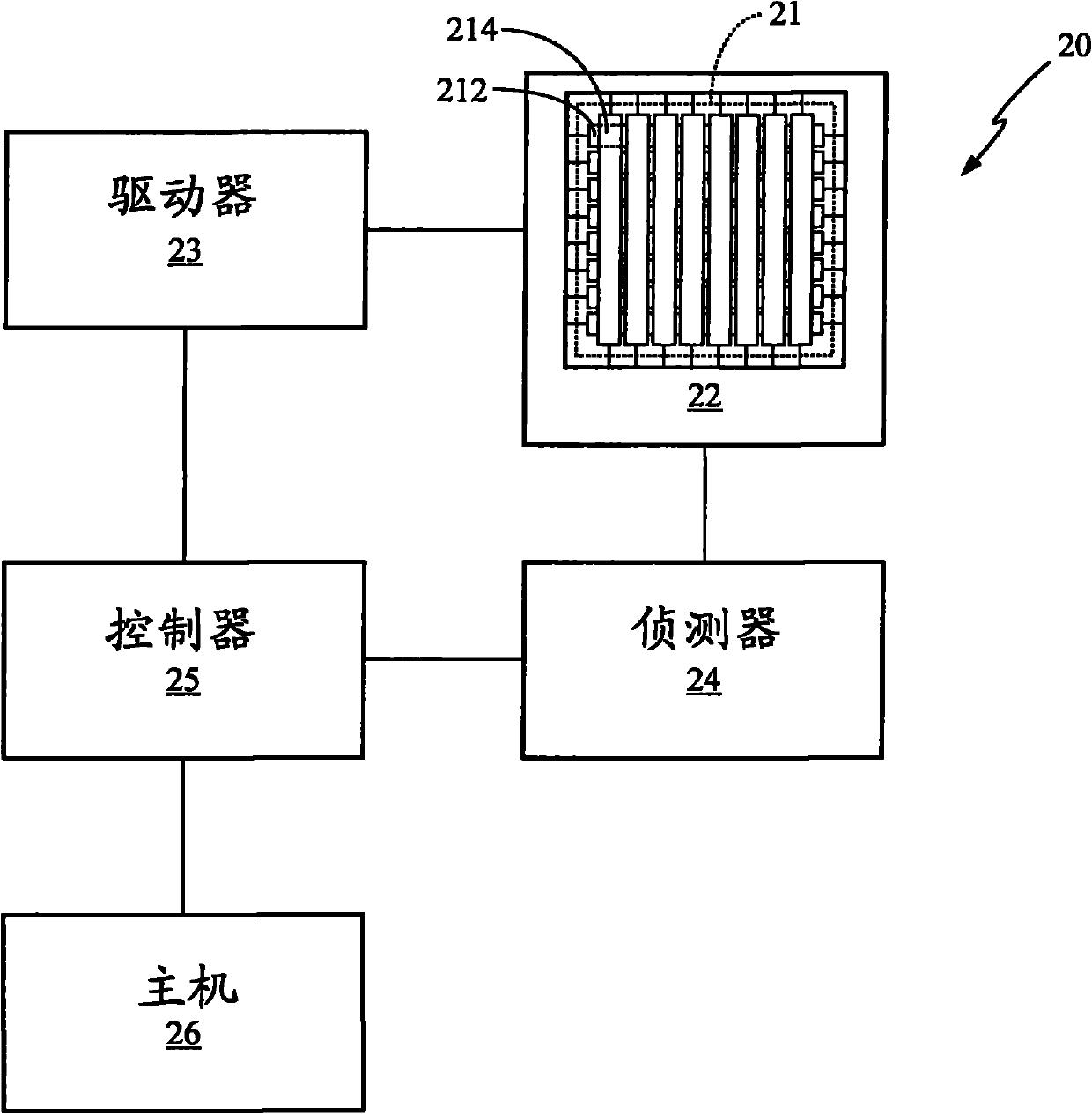
[0100] Please refer to Figure 2A As shown, the present invention provides a position detection device 20, including a sensor (Sensor) 21, a selector (Selecting Device) 22, a driver (Driving Device) 23, a detector (Sensing) 24, a controller (Controlling Device) 25, Host (Host) 26.

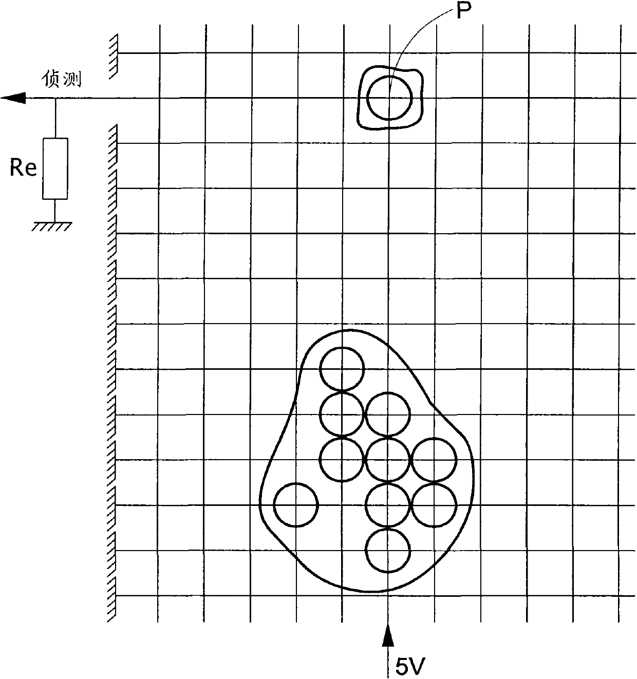
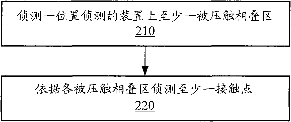
[0101] Refer again Figure 2B As shown, the present invention provides a method for multi-point position detection. First, as shown in step 210, at least one depressed intersecting region (depressed intersecting region) on a device 20 for position detection is detected...


PUM


Abstract

The invention provides a position detection device and a method thereof. The position detection device comprises a plurality of intersecting regions composed by a plurality of conductive strips, wherein a pair of conductive strips intersected with any intersecting regions forms a pressure touching intersecting region when a contact point is formed by electrically contacting. Based on the pressure touching intersecting region, each pressure touching can be determined. The total touching resistance of each pressure touching can be determined by judging the contacting resistance of each pressure touching intersecting region. The total contacting resistance of the pressure touching of a cross-phase intersecting region is the parallel connection resistance of the contacting resistance of all intersecting regions composed by relative equal pressure touching.

Description

technical field [0001] The present invention relates to a device and method for position detection, in particular to a device and method for pressure-touch position detection. Background technique [0002] In U.S. Patent Publication No. US2007 / 0198926, Jouget et al. disclosed a device for pressure-contact position detection, which includes an upper electrode layer and a lower electrode layer. The upper and lower electrode layers respectively include a plurality of parallel arrays in different directions. Wires, and insulating particles (spacer) are distributed between the upper and lower layers, so as to separate the upper and lower electrode layers. Therefore, when the upper electrode layer is pressed down, part of the wires of the upper electrode layer will contact with the wires of the lower electrode, wherein all the wires of the lower electrode layer are grounded. The wires of the upper electrode layer are driven sequentially, and when any wire of the upper electrode l...

Claims


Application Information

Patent Timeline
Patent Type & Authority Applications(China)
IPC IPC(8): G06F3/041
CPCG06F2203/04104G06F3/0418G06F3/047
Inventor 叶尚泰陈家铭何顺隆
Owner EGALAX EMPIA TECH INC
Why Eureka
Try Eureka