Organic light emitting display panel

A light-emitting display and panel technology, which is applied to organic semiconductor devices, electrical components, electric solid-state devices, etc., can solve the problems of large metal resistance, weakened voltage drop, uneven display, etc. The effect of pressure drop

Inactive Publication Date: 2019-08-09
SHENZHEN CHINA STAR OPTOELECTRONICS SEMICON DISPLAY TECH CO LTD
View PDF5 Cites 10 Cited by
  • Summary
  • Abstract
  • Description
  • Claims
  • Application Information

AI Technical Summary

Problems solved by technology

[0002] In self-luminous display panels, especially top-emitting device structures, the cathode usually uses an extremely thin metal layer to obtain higher transmittance, but the extremely thin metal itself has a large resistance, causing a voltage drop (IR Drop) of the cathode voltage , leading to uneven light emission of the panel, it is usually adopted to add auxiliary cathode

Method used


Image

  • Organic light emitting display panel
  • Organic light emitting display panel

Examples


Embodiment Construction

[0023] The following will clearly and completely describe the technical solutions in the embodiments of the present invention with reference to the drawings in the embodiments of the present invention. Apparently, the described embodiments are only some of the embodiments of the present invention, but not all of them. Based on the embodiments of the present invention, all other embodiments obtained by those skilled in the art without creative efforts fall within the protection scope of the present invention.

[0024] The terms "first", "second", "third", etc. (if any) in the description and claims of the present invention and the above drawings are used to distinguish similar objects and not necessarily to describe a specific order or sequentially. It should be understood that the items so described are interchangeable under appropriate circumstances. Furthermore, the terms "comprising" and "having", as well as any variations thereof, are intended to cover a non-exclusive in...


PUM


Abstract

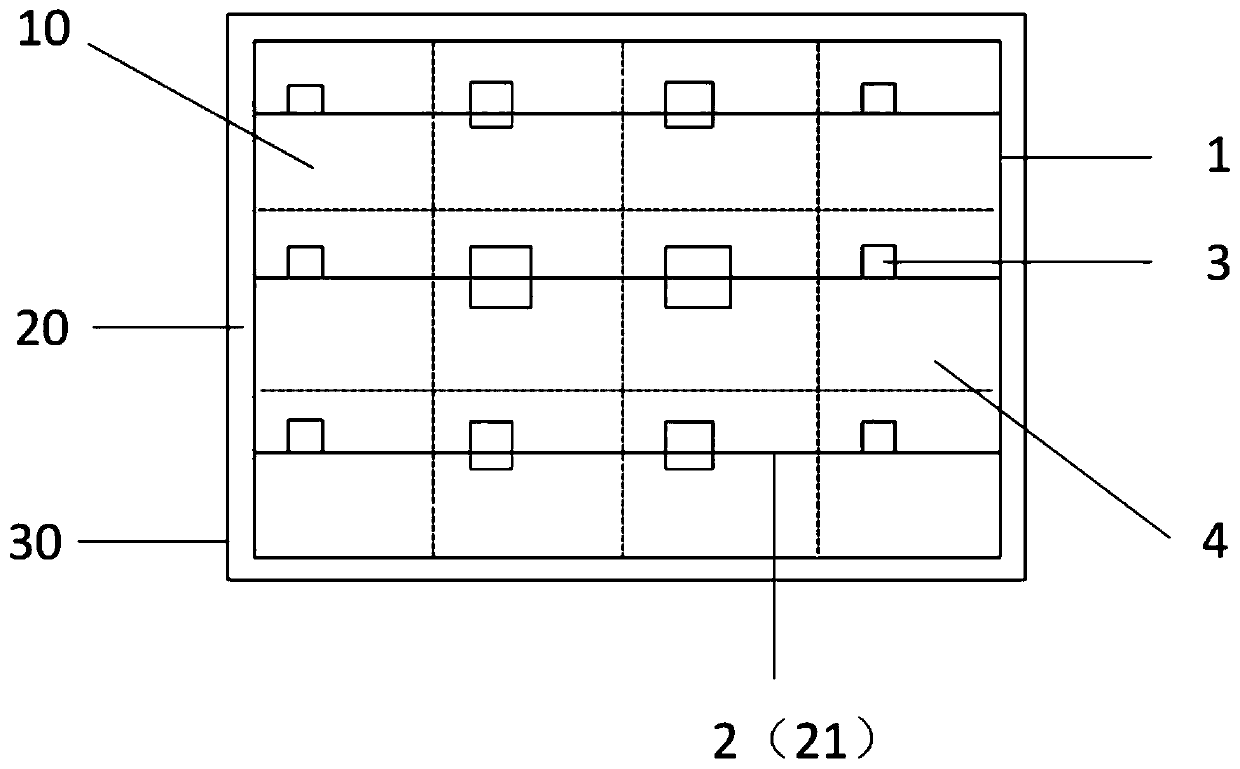
The invention discloses an organic light emitting display panel having a display region and a peripheral region. The organic light emitting display panel includes a substrate, multiple sub pixel regions and a cathode arranged on the display region, an auxiliary cathode and multiple contact holes, wherein an input end of the cathode extends to the peripheral region, the cathode and the auxiliary cathode are electrically connected through the contact holes, each sub pixel region corresponds to at least one contact hole, the further the contact hole is from the input end of the cathode, the larger the size of the contact hole, and at least one of the contact holes is arranged in each of the sub pixel regions. The display panel is advantaged in that through designing the contact holes with therelatively large size, contact impedance of the auxiliary cathode and the cathode can be reduced, the cathode voltage can be better reduced, the actual cathode voltage is made to be closer to the input cathode voltage, and uniformity of display brightness is improved.

Description

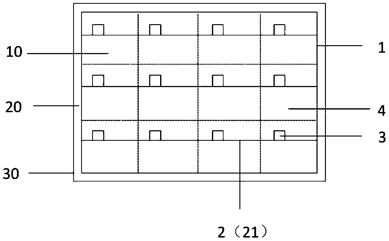
technical field [0001] The present invention relates to the field of display technology, in particular to an organic light emitting display panel. Background technique [0002] In self-luminous display panels, especially top-emitting device structures, the cathode usually uses an extremely thin metal layer to obtain higher transmittance, but the extremely thin metal itself has a large resistance, causing a voltage drop (IR Drop) of the cathode voltage , leading to uneven light emission of the panel, it is usually adopted to add auxiliary cathode wiring in the pixel to weaken the influence of voltage drop (IR Drop), such as figure 1 As shown, the contact hole of each pixel is the same, but the same contact hole design can only reduce the voltage drop (IR Drop) to the same extent, but the degree of voltage drop (IR Drop) is different in different positions of the panel, and there is still display unevenness sex issue. Therefore, need to provide one kind badly, to solve the a...

Claims


Application Information

Patent Timeline
IPC IPC(8): H01L27/32H01L51/52
CPCH10K59/122H10K59/131H10K50/824H10K50/828H10K59/1315H10K2102/3026
Inventor 肖翔
Owner SHENZHEN CHINA STAR OPTOELECTRONICS SEMICON DISPLAY TECH CO LTD
Why Eureka
Try Eureka